Update #15 - EV conversion initial plan #
At the end of August, I attended the 4 day EV car conversion course run by Damien Maguire and Kevin Sharpe. It was absolutely fantastic. I learnt a shedload. I highly recommend it to anyone thinking of doing an EV conversion.
One of the big takeaways from the course was the focus on opensource collaboration. There is a growing community of people out there, working together to share knowledge and develop open solutions to motor inverters, charging, battery management and so on. In my day job I’ve worked a lot with open source, so, this is a no brainer to me.
One of the other big things emphasised on the course was the benefits of re-using parts from other cars over buying EV ‘products’. If you use a part from a Prius, say, because there were so many of them made, should anything go wrong with your part, you have a very good shot at repairing or replacing it in the future. Whereas, products produced by EV conversion companies are produced in far smaller numbers. If something goes wrong you are likely on your own.
With all of that in mind, I’ve been doing some shopping.
Batteries #
One important consideration when choosing a battery is voltage. A given battery pack uses some combination of wiring the cells and modules in series and in parallel to end up with a desired pack voltage. To be useful, your pack needs to put out over 300V.
Using a pack from a crashed EV is an obvious place to start looking for batteries. Of course, with this approach, the one gotcha is that the pack will be wired to put out 300+V, so, really you need to use the whole pack. If you split the pack, you cut the voltage down at the same time. But buying a whole pack can still be quite expensive. It is usually the most expensive component in a conversion.
You may want to start with a smaller capacity to minimise your initial cost outlay. So, what’s the answer? Well, there are a lot of PHEVs that have been on the market for a while now which use lithium ion batteries. They have relatively small packs, but they are wired in such a way to produce a decent voltage.
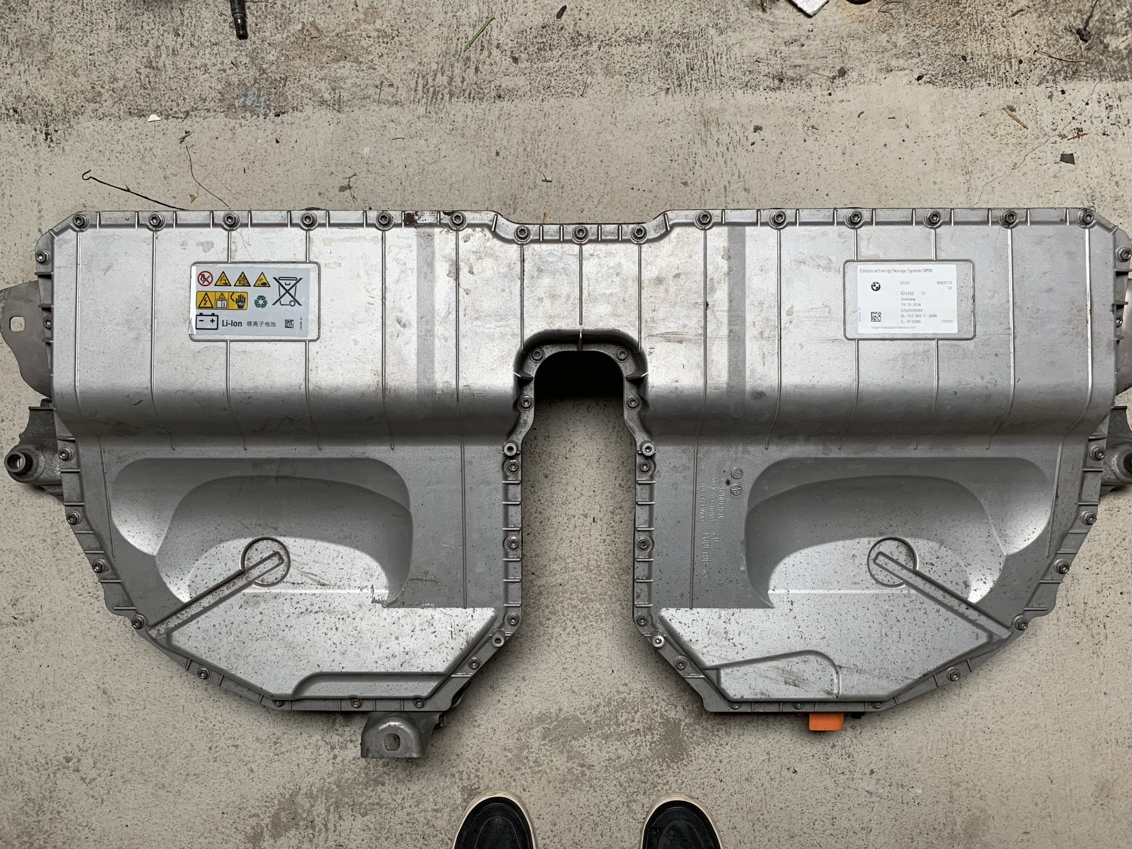
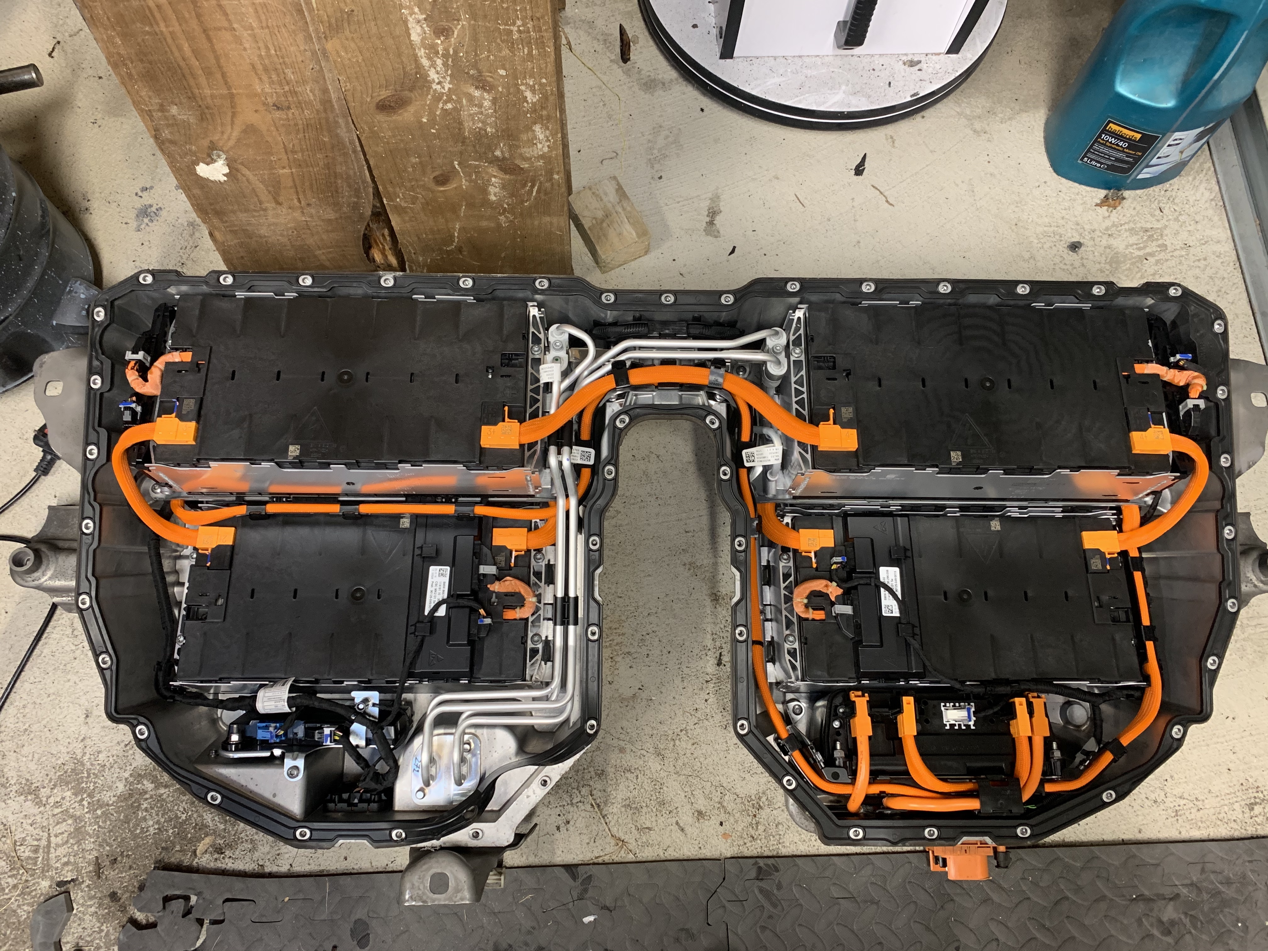
I’ve bought myself a battery pack from a crashed BMW 5 series hybrid. Nominal voltage is 351V. It has a capacity of around 9kWh. I expect this will give me up to 50km of range. I would like more than that, but, one of these packs are good enough to prove the design without having to outlay too much money up front.
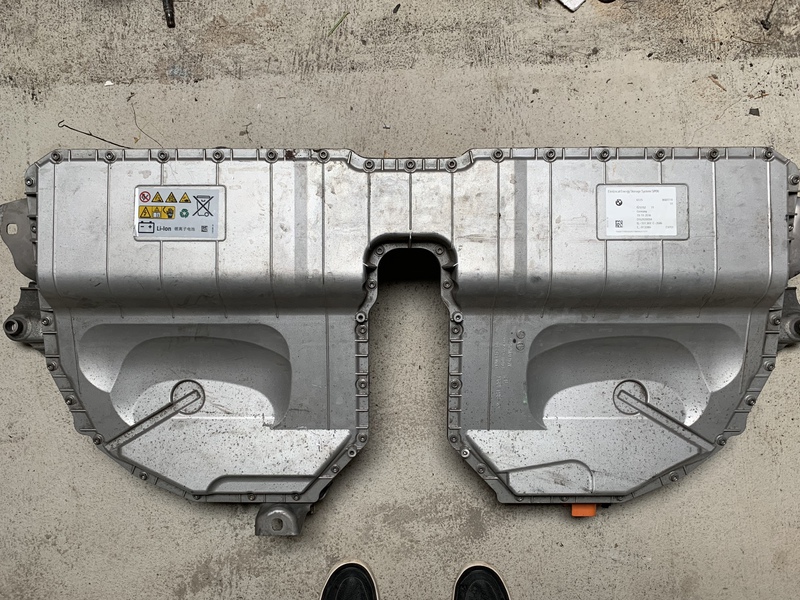
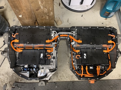
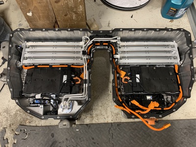
This pack has 6 modules inside of it. Each module has 16 cells - giving the pack a total of 96 cells. It also includes a lot of extra stuff I’m not going to need. For example, there’s a liquid cooling loop. The pack is built this way because, in a PHEV application, the battery is constantly oscillating back and forth between charging and discharging. This generates a lot of heat, hence the extra cooling. However, in a pure EV application, at any given time, the batteries will only ever be charging or discharging. You will be driving the car around - discharging the battery as you go. Or, you will be parked, charging the battery up. The only slight exception here is regenerative breaking, but that shouldn’t be significant.
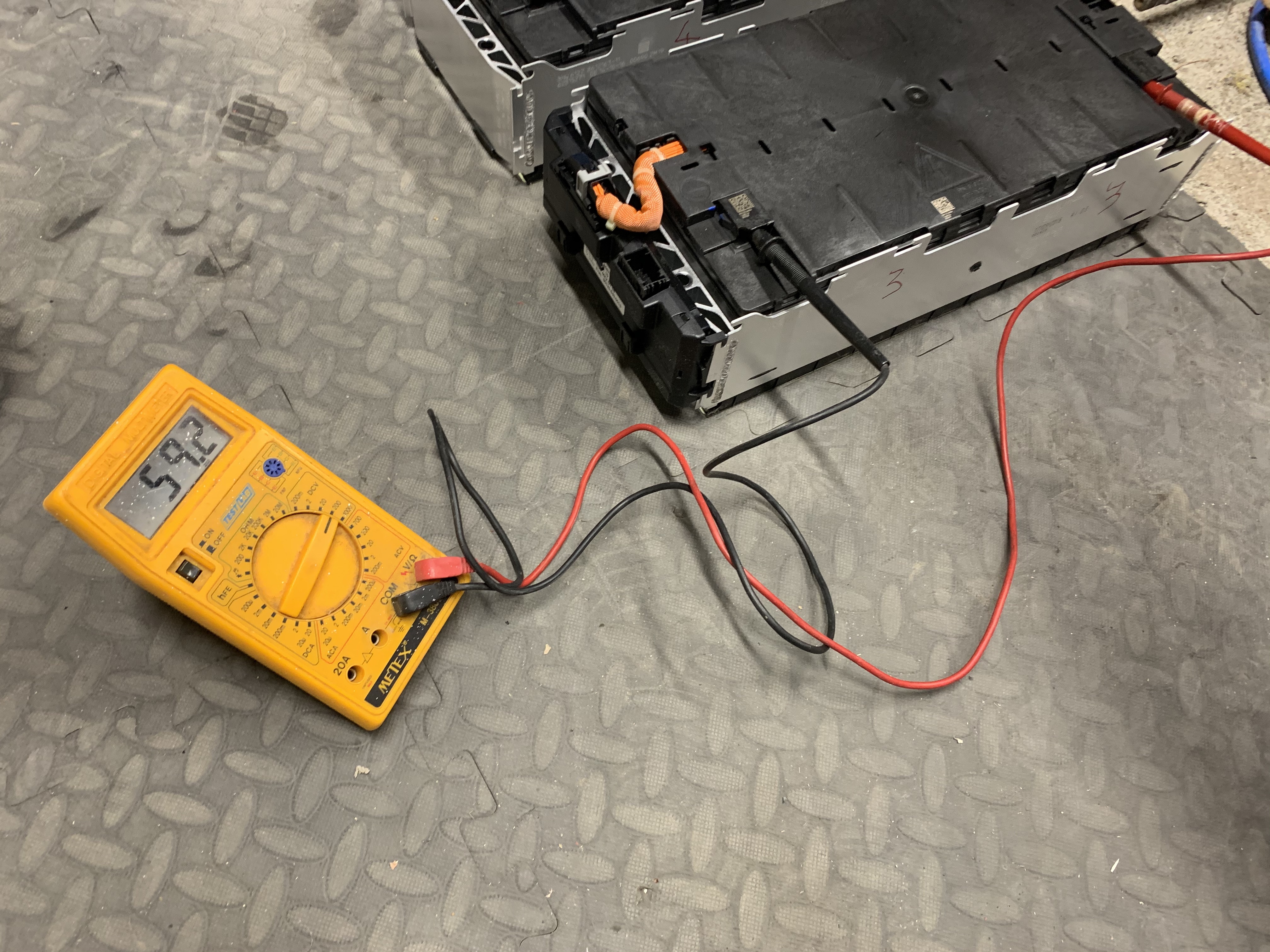
So, I’ve started to break down this pack. I’m going to pull out the six modules and build a new battery box to house them in. This will allow me to re-shape the pack into a form more suitable for me and dump the cooling loop.

Each module measures approx 400x200x100 mm. So, I’m trying to figure out where to put this pack. I have three options.
- The engine bay. There is loads of space here. I could build a flat 2x3 battery box. This would leave room to stack another battery box on top later on to add range. Plus the front springs are expecting around 175kg of engine that’s not going to be there any more.
- The fuel tank. The muffler used to sit right behind the fuel tank. I think I could extend the fuel tank back a bit where the muffler used to be and fit all six modules from the BMW pack in there.
- Behind the back seat there is a space measuring approx 1100x400x300 mm.
Inverter #
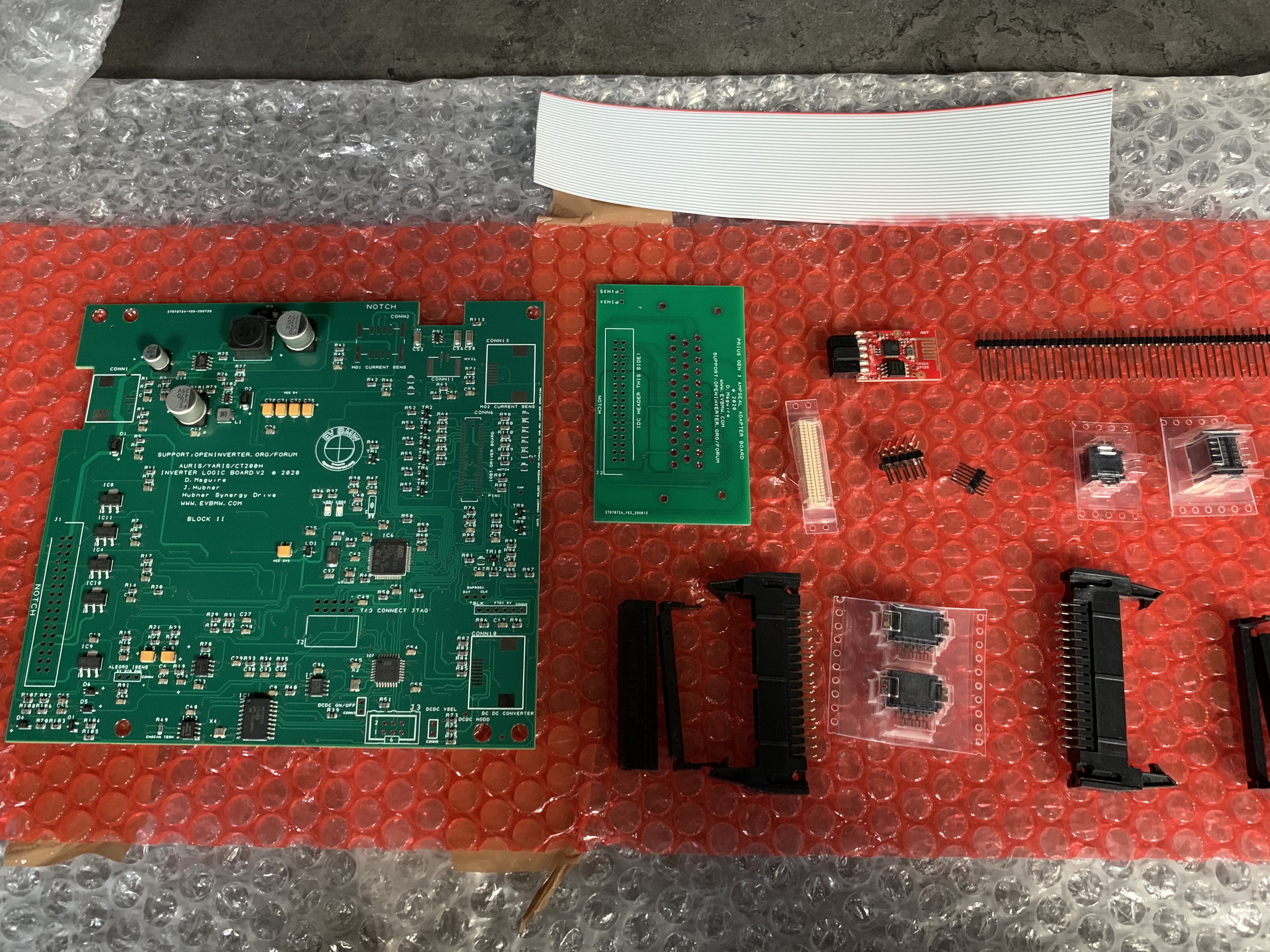
An inverter does multiple things. First and foremost, it takes DC current from the batteries and converts it into 3-phase AC to run your motor. I’ve bought myself a second-hand inverter from a Prius-C. This is the same inverter found in hybrid Auris and Yaris cars.
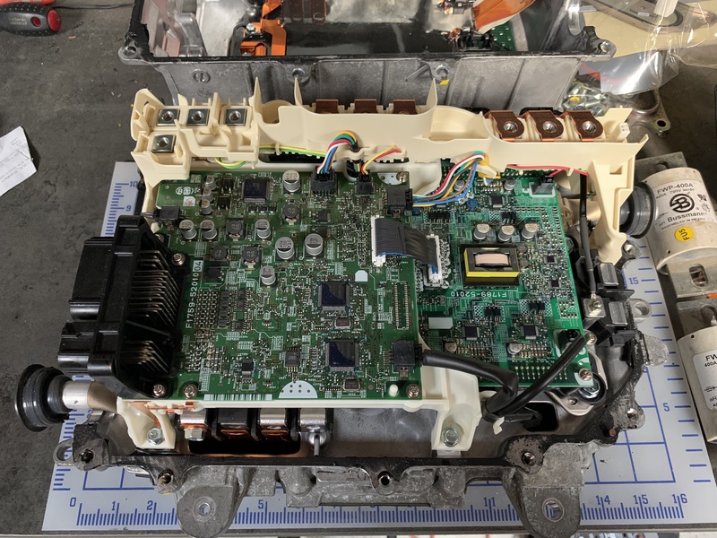
Inside the case of the inverter you’ll see two boards. The top board is the ‘brain’ of the inverter. On the left hand side you’ll see the big black connector where this brain board links into the rest of the car. I’m going to do a brain transplant on this inverter. I’ve bought myself a new brain board. The hardware was developed by Damien Maguire and the openinverter software by Johannes Hübner.

The inverter also has a 12V output for the accessories in the car (e.g., dashboard, battery charging, lights). There’s not much in my case, but I’ll need it nonetheless. This fills in for the alternator that would normally be in a car with an internal combustion engine. I’ll still need a 12V battery, but only to power up the inverter initially to start the car. So, I’m going to look around for small 12V batteries, from, for example, motorbikes to save on space.
This inverter also has a DC-DC converter, which can be useful for multiple things, but more on that later.
Motor #
It turns out that a lot of hybrid cars have really great motors. Or, to be more precise, two really great motors. In a typical hybrid, the internal combustion engine spins one motor (motor-generator 1, or MG1) which generates electricity. This energy is stored in the batteries. There is a second motor (MG2) which takes energy from the batteries and provides traction. But, in a pure EV setting, we can, with little or no modification, use both MG1 and MG2 for traction.
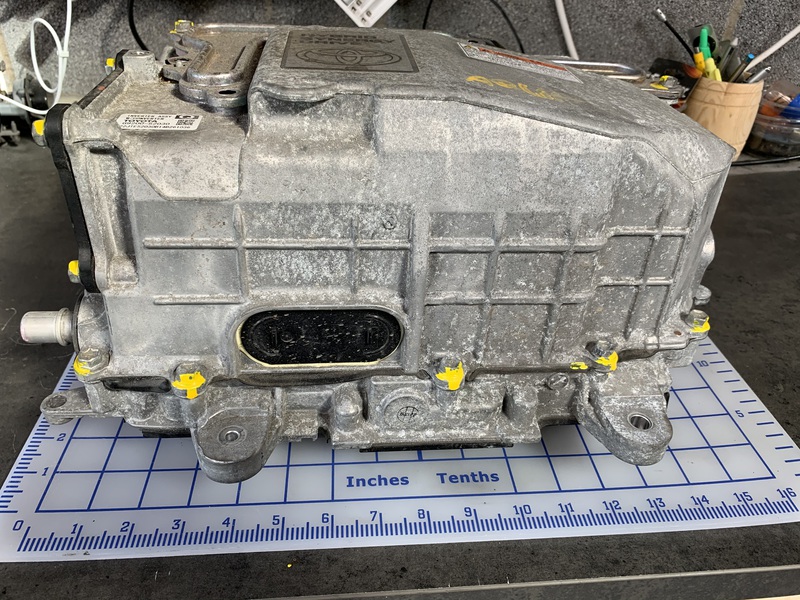
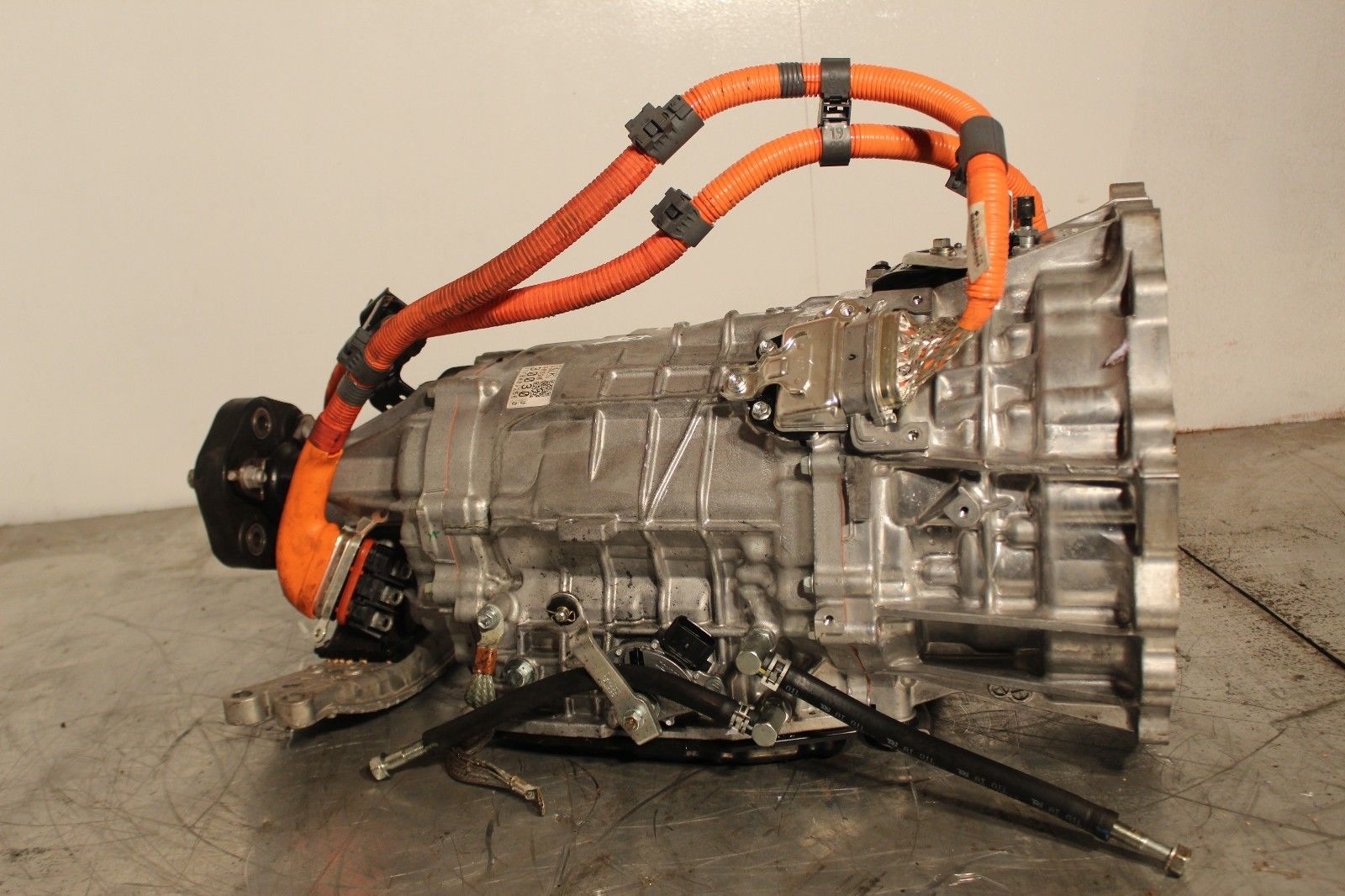
So, one approach that people have been using in their conversions is to take the gearbox from a hybrid car (where the motors are housed) and use that as the power plant for their conversion. The mustang is a rear wheel drive car. One gearbox which is becoming popular to use for rear wheel drive cars is the gearbox from a Lexus GS450h. Now, I didn’t have much luck in finding a GS450h gearbox straight away, but, the gearbox from the GS300h started to attract my attention. It’s very similar in design. The main way that the GS300h gearbox seems to differ from the GS450h gearbox is that the GS450h has an internal and an external oil pump while the GS300h has only an internal pump. And, as it turns out, when using the GS450h in pure EV mode, the external oil pump is essential. The internal pump is driven by the rotation of the internal combustion engine. But, when used in pure EV mode, the input shaft to the gearbox is locked in place. So, we depend on the external pump to create oil pressure.
Regardless, I took a bit of a gamble and bought this gearbox from a GS300h. As far as I’m aware, no one has used this gearbox in an EV conversion, so, hopefully I can lay some groundwork which others can benefit from.
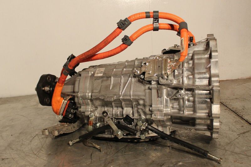
MG1 is located in the bell housing. MG2 is located in the central section. I drained the transmission fluid and opened up the bell housing end. My objective was to see what drives the internal oil pump. Is it possible to turn the oil pump without the internal combustion engine?
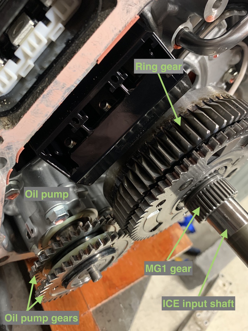
You can see the oil pump in the lower left of this picture. As you can see, there are two gears driving the pump. One from the ICE and the other from MG2 (via the ring gear). These gears have little one-way clutches on them, so, even if one of them is spinning backwards, as long as one is spinning forwards, then the pump will make pressure. So, it looks like I don’t need to worry about this gearbox not having an external oil pump.
Turning MG2 and holding the input shaft still.
Closer look at how the oil gear clutches work.
What turning MG1 will do when holding the input shaft still.