Update 18 #
2021-08-10
No update in a long time. I’m going to try and do updates more often.
My high voltage junction box is almost complete.
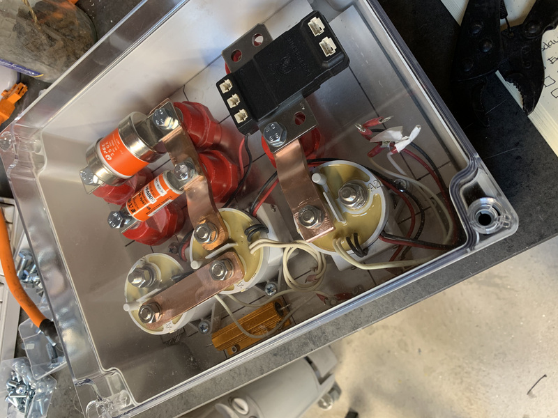
You can see the three kilovac contactors - the white cylindrical things. These are used to connect/disconnect the battery from the inverter. One is for the negative side of the battery, one is for the positive, and the third is a precharge contactor. The precharge resistor is the orange thing. The precharge contactor closes before the main positive contactor. It prevents a big inrush of current into the inverter as you apply power by running it through the precharge resistor.
The black thing is an ISA shunt. This is a coulomb counter. It keeps a tab on how much energy passes out of the battery when driving and how much passes in while charging. This will effectively be my ‘fuel’ gauge. It will give me a very accurate view of how much energy is left in the battery at any one time. The two ports at the bottom are CAN bus ports (and power). The shunt transmits power usage information out on the CAN bus port while powered on.
The two orange things are my fuses. The fatter one is the traction fuse. This was pulled from the BMW battery box.
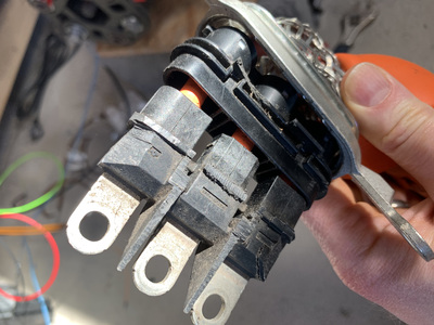
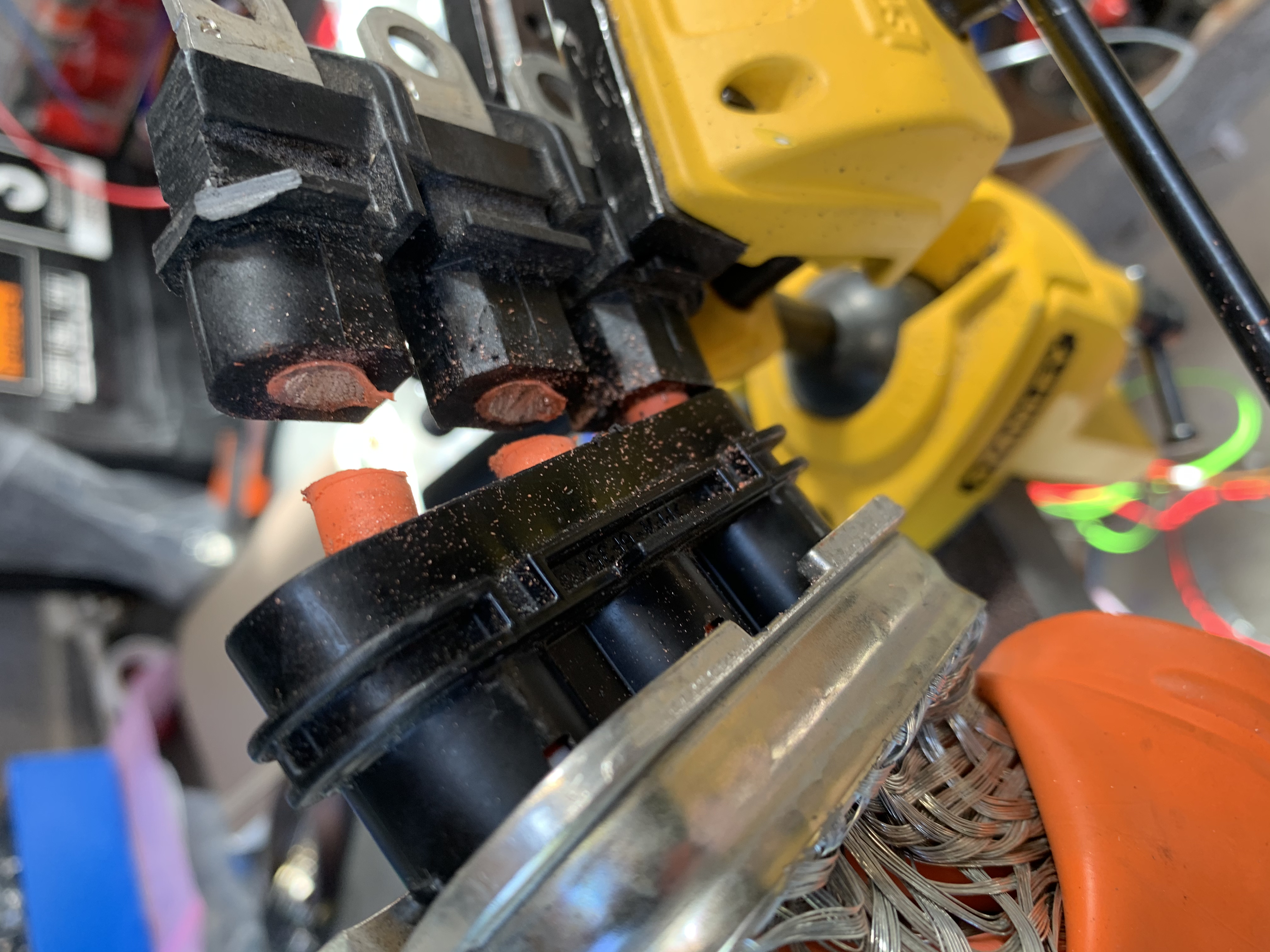
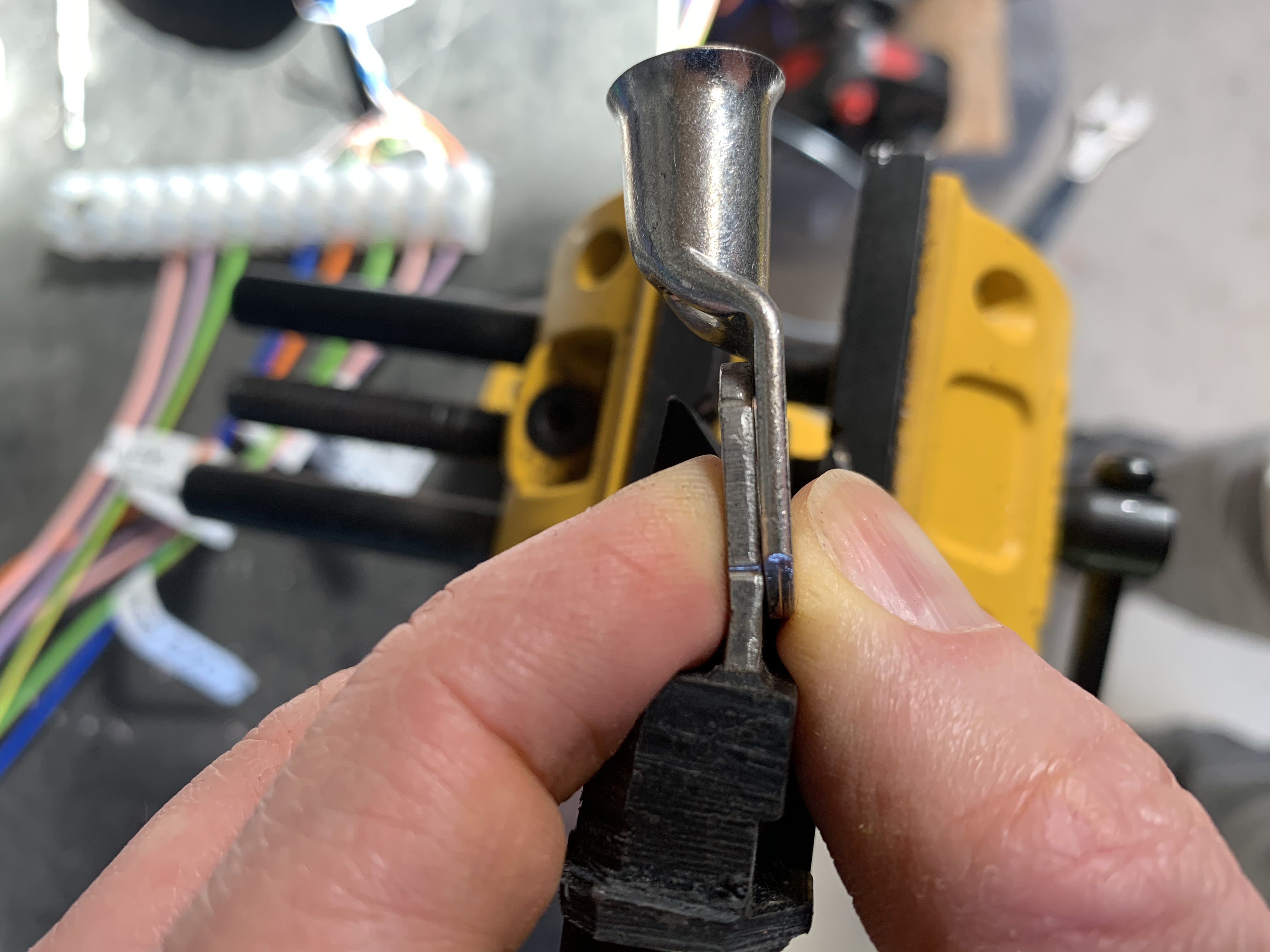
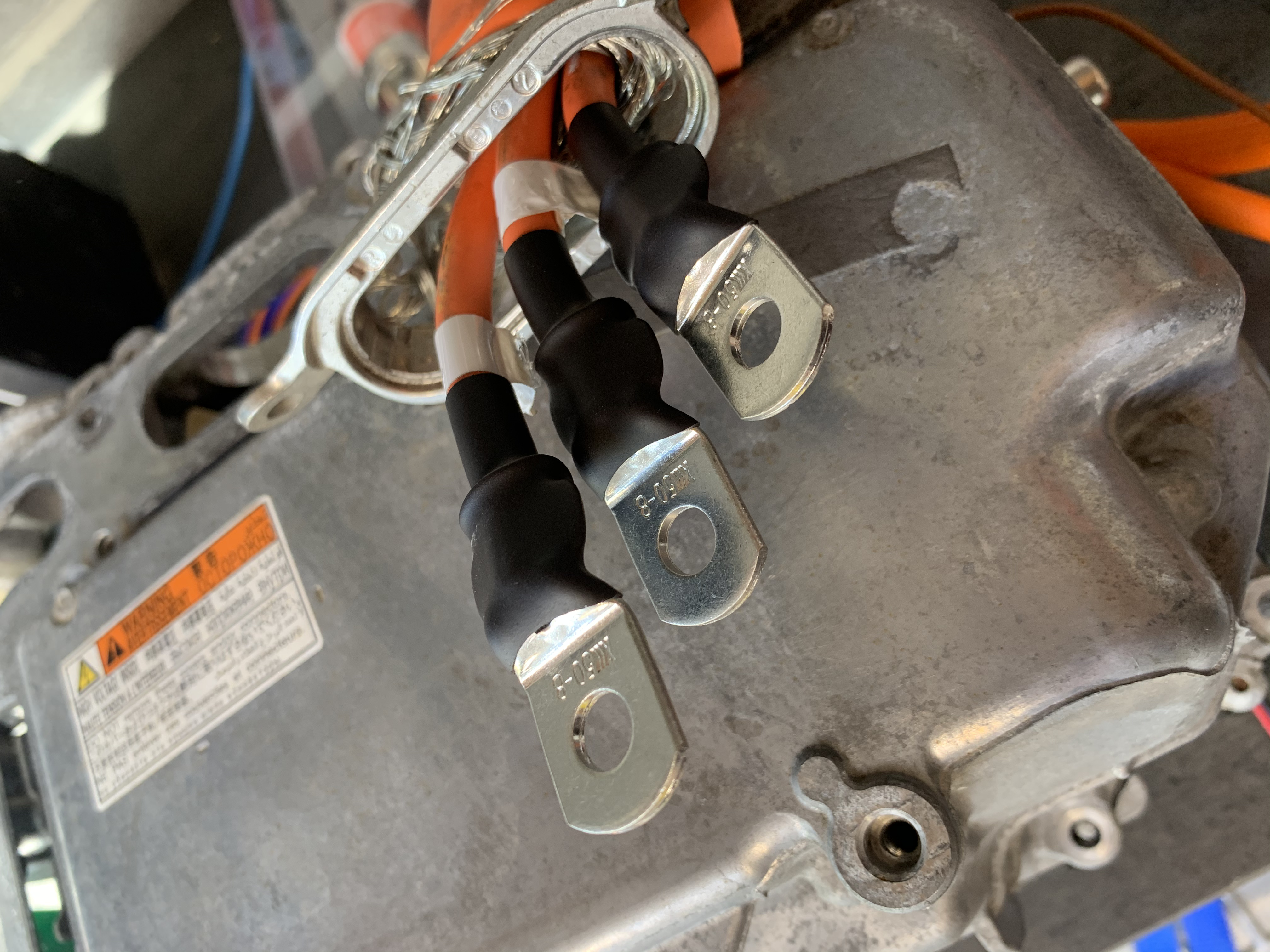
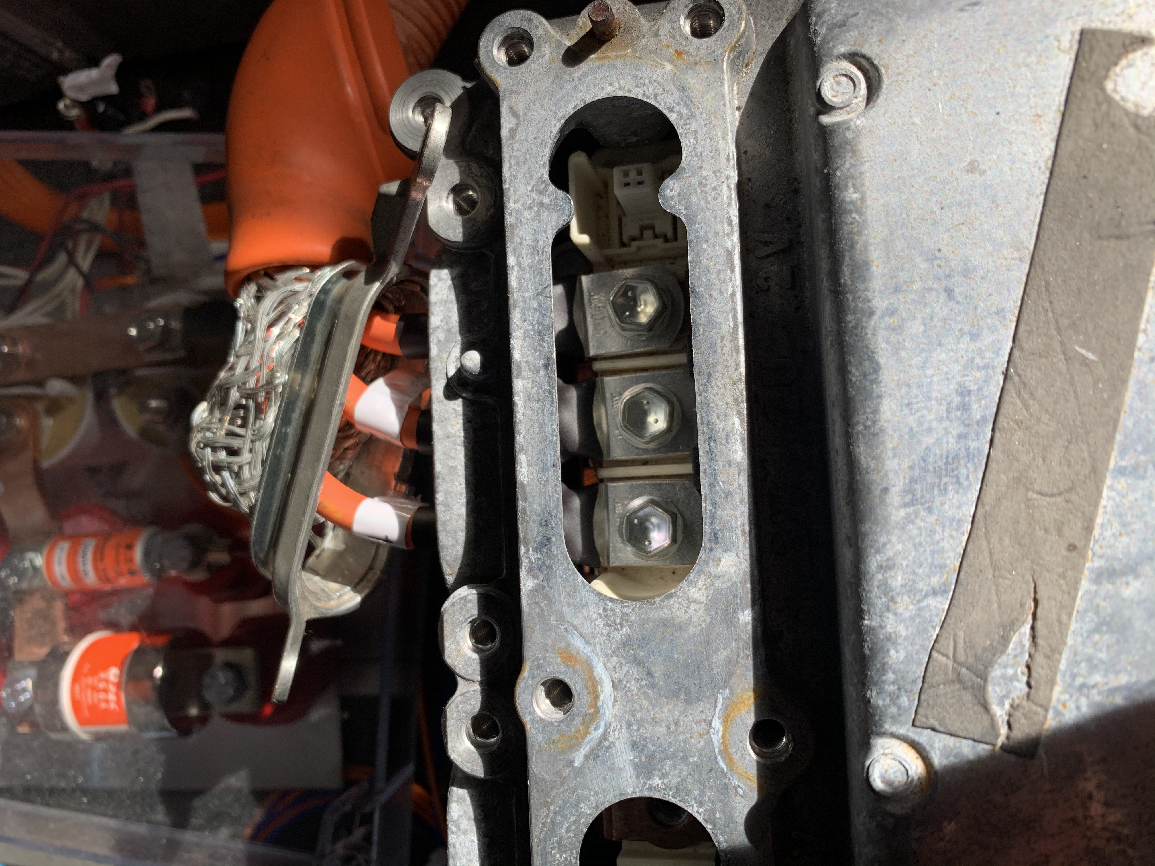
In the FOC tuning process, you need to pass a fair amount of current into the motor when you’re trying to find the correct syncofs value. So, I needed to adapt the three phase cables that came with the CVT (motors) so that they could fit inverter. The plug on the inverter end of these cables is designed for the inverter in the Lexus, not for my Prius inverter. So, hacksaw to the rescue. Chop off the plug and crimp on some normal lugs.


I’ve been trying to get the inverter configured correctly to spin the motor using the FOC OpenInverter firmware.
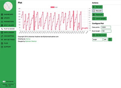
The first step is to get the wiring of the resolver circuit right. There are six cables in total involved. One pair is the exciter signal which comes from the inverter to the resolver. The other two pairs are the sine and cosine feedback from the resolver to the inverter. These give the position of the rotor. After trying the different permutations many, many times I think I have it right. You can verify this by slowly turning the output flange by hand while plotting the angle of the rotor in the OpenInverter web interface. It should move from zero up to 360 degrees and then wrap around.
Once you have this right, you should be able to spin the motor by applying a little manualid current. Here’s a video showing what I’m getting.
The motor won’t spin up from a dead stop. But if I give it a little push it will start. It does spin faster if I apply more current. But, since there is no load on the flange, I think I should be seeing it spin up and up more - not being locked at a constant rpm like this.
There are two configuration settings that I don’t know for sure, and have just guessed. These are the pole pairs of the motor and the pole pairs of the resolver. I’ve started with a guess value of 4 for the pole pairs. This is based on the fact that the gs450h CVT has 4 pole pairs. The gs450h CVT is older, but very similar to the gs300h CVT I’m using. But this could be wrong.
I found a procedure on the OpenInverter forum here to find the number of motor pole pairs and the number of resolver pole pairs.
What’s next
- Fully refill the oil in the CVT. There is only 1L in there. There should be around 3.5L.
- Just realised the that the motor is spinning backward in the video above. I put little ‘forward’ stickers on the output flange, but put them on the wrong way. It doesn’t really matter at this stage. Finding the right syncofs value will correct this I think.
- I managed to blow the precharge resistor again by pushing too much current into the motor … again. I think that makes three times now. I need to swap out the precharge resistor.
- Try to determine the correct settings for motor pole pairs and resolver pole pairs.