Update #19 - motor pole pairs and resolver pole pairs #
The motor is not spinning up from a dead stop. I can give it a little push and it will start to spin, but it stutters and makes some pretty unpleasant noises. One setting that I know that I don’t know is the motor pole pairs and the resolver pole pairs. I’ve been guessing at 4 for the motor pole pairs based on the fact that this motors older brother the gs450h has 4 motor pole pairs. But this could be wrong.
I took the CVT apart, so I know that the ratio between the MG2 motor and the output shaft is 3.3333. So, working backwards, the output shaft should move 108 degrees (360 / 3.3333) for every one rotation of MG2.
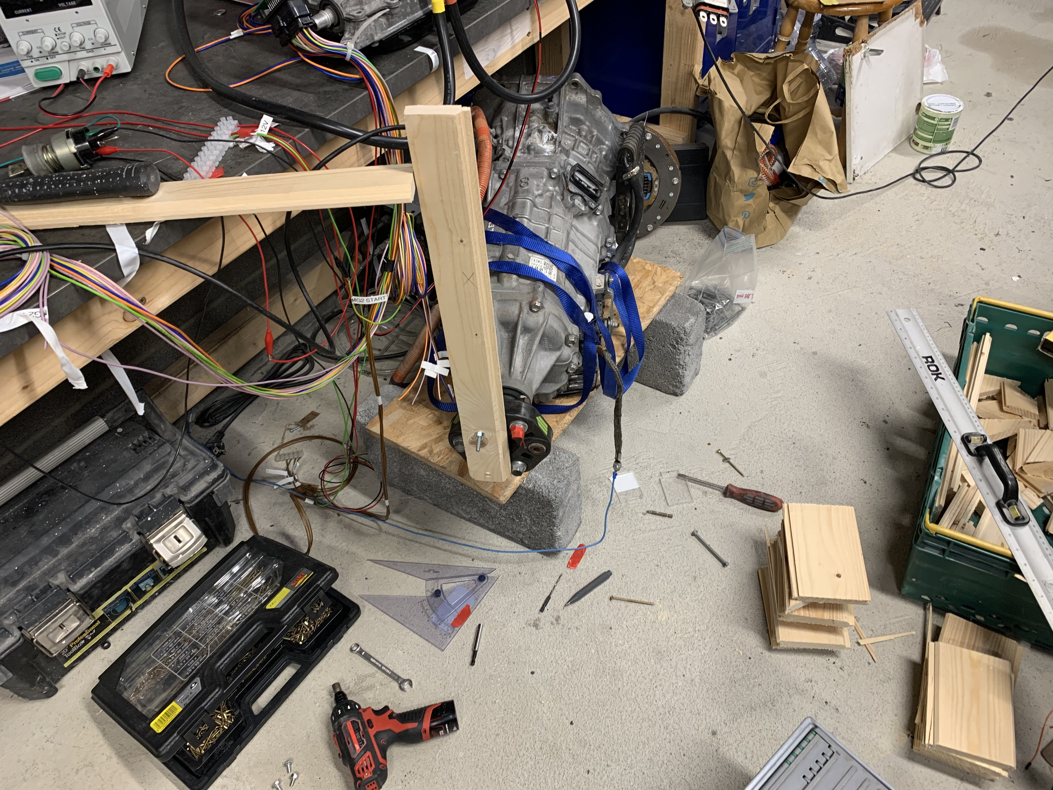
I bolted a bit of wood to the output flange to act as a ‘clock hand’. I then blocked the hand so that it could only move approximately 108 degrees. Not very accurate, but close enough. I then watched a plot of rotor angle as I slowly swept the arm through one motor revolution. I recorded how many revolutions the firmware thought the motor did with that combination of motor/resolver pole pairs. I repeated the procedure with different combinations of polepairs and resolverpolepairs.

My 'clock' arm attached to the output flange and blocks of wood acting as stops marking out 108 degrees
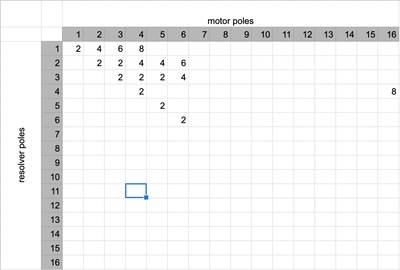
How many turns of the motor do I see for different combinations of motor pole pairs and resolver pole pairs.
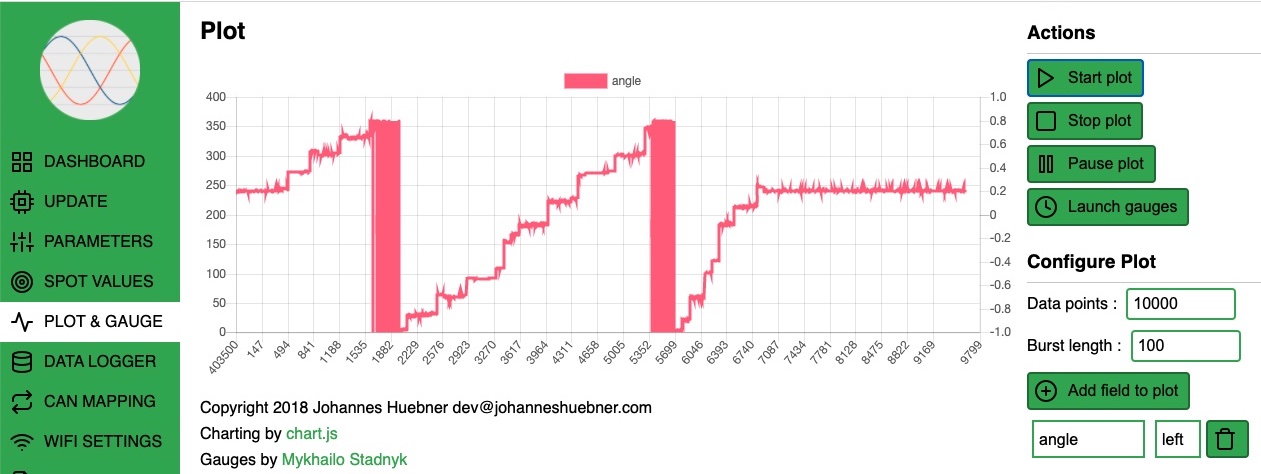
As you can see, I didn’t try every combination, but enough to see a trend. At best, I was getting two turns for every sweep. I am expecting to see only one. Here’s what a plot would typically look like for any of the 1:1 polepair/resolverpair settings (e.g. 4 pole pairs and 4 resolver pairs, or 2 polepairs and 2 resolver pairs).

Based on my table I would expect having double the resolver pairs of the motor pairs would get me closer to the right configuration, but the OpenInverter firmware doesn’t seem to like that. It just always gives me zero degrees when I try to set resolver pole pairs > motor pole pairs.
So, I thought, OK, time to backtrack. Maybe I don’t have the correct resolver wiring. There are only four possible permutations of the four sin, cos, enc 1, and enc 2 cables. And that’s when things got weird. The three wrong wiring combinations should give me an angle that jumps around. But that’s not what I saw. I need to go back and verify this, but it looked like every resolver wiring combination was giving me the same two motor turns per 108 degree sweep. Which doesn’t make any sense.