Update #21 - yet more resolver/polepairs/respolepairs debugging #
I’m still working on getting my resolver wiring and my polepairs/repolepairs settings right.
I got a little help from the OpenInverter community. It seems that it the ‘angle’ value tracked by the OpenInverter board is the resolver angle. This ’electrical’ angle is not the same as the actual rotor angle. It can be a multiple of the actual rotor angle. So, the fact that I’m seeing two full ’electrical’ revolutions for one actual physical revolution of the rotor is fine. Nothing is wrong about that.
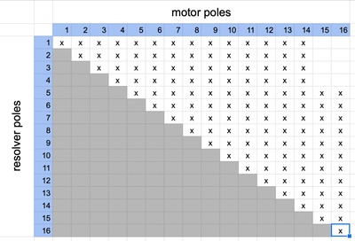
So I’ve started systematically testing all combinations of polepairs, respolepairs, and the resolver wirings. polepairs and respolepairs can be any value between 1 and 16. But polepairs must always be greater than or equal to repolepairs. That makes for 136 possible options.
The resolver wiring consists of three pairs of cables. The first pair is the exciter pair. It doesn’t matter if you get the polarity flipped on this pair. It will just mean the the polarity on the other two pairs will be flipped. The other two pairs are the sine and cosine feedback signals from the resolver. To figure out the angle the OpenInverter code gets the arctan of the sin/cos signals. So, it doesn’t matter if you swap the sine and cosine pairs. So the only trial-and-error guessing you need to do is the polarity of the sine/cosine pairs. This gives you four possible wiring combinations. sin+, sin-, cos+, cos- OR sin+, sin-, cos-, cos+ OR sin-, sin+, cos+, cos- OR sin-, sin+, cos-, cos+.
I’ve tried all polepair/respolepair permutations for one resolver wiring combination. What I noticed is that when the polepairs setting was twice the respolepairs setting, I could get the motor to spin a bit. It was very clunky and rough, but it would spin. It feels like this relates in some way to the two electrical revolutions per ‘real’ revolution I was seeing.
I also managed to blow yet another pre-charge resistor. So, I’m using a bulb now in place of a pre-charge resistor. It does the same job - provides a resistance to prevent a big inrush current which would blow the big capacitor in the inverter.