Update #31 - Cowl tank installation + BMS #
2023-03-01
It has been a long time with no update!
The next job on the agenda was to put in the brand new cowl tank that I bought. The old one was completely rotten and unrecoverable. This is a very common area for rust and rot in these cars. Leaves and other debris gets lodged in the tank. This damp stuff sits up against the cowls and slowly rots them away.
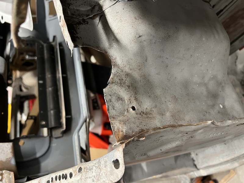
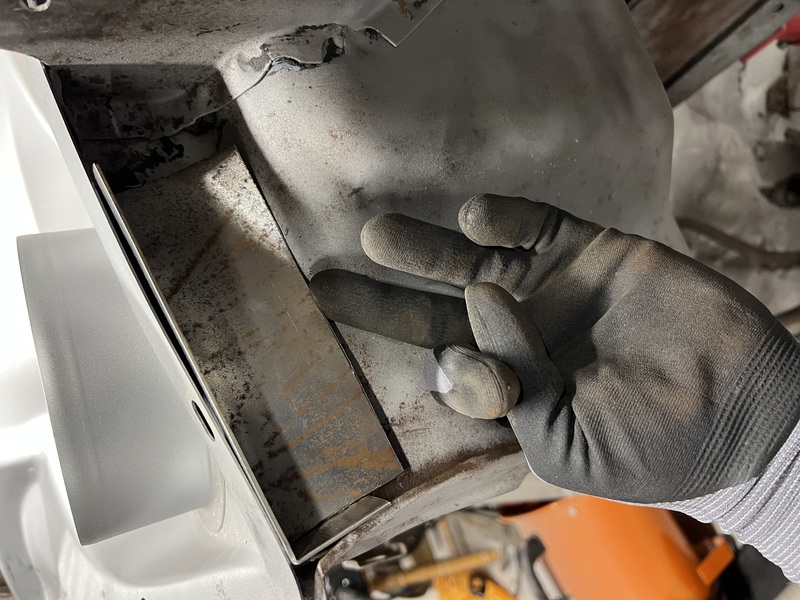
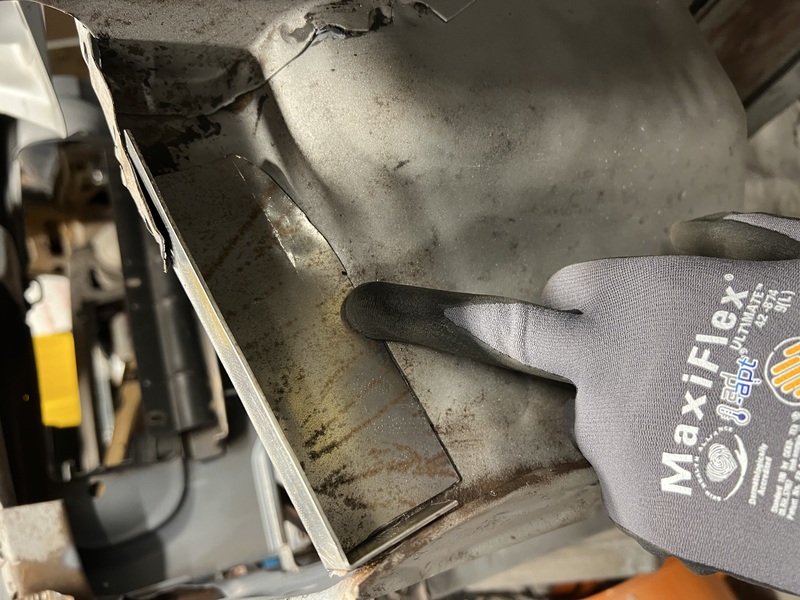
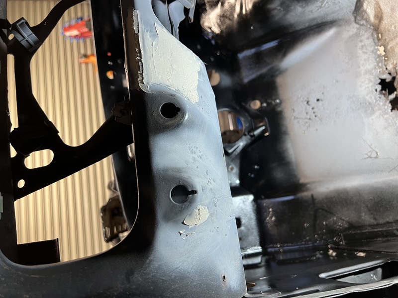
But before I could get stuck into installing the new cowl tank, the firewall needed a bit of a repair job. A bit on the right side had some sort of puncture damage and some rot that needed patching.
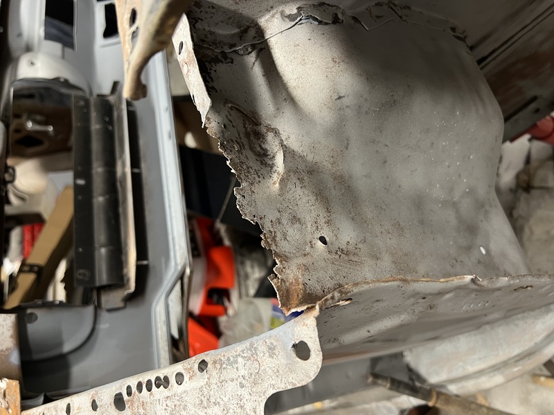
First, a little cleanup to remove the useless bits to see more clearly what I was working with.
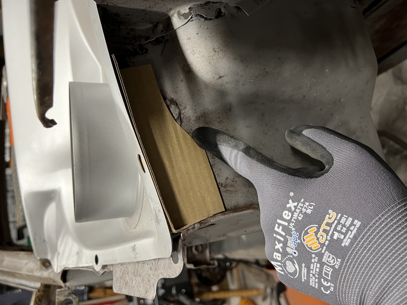
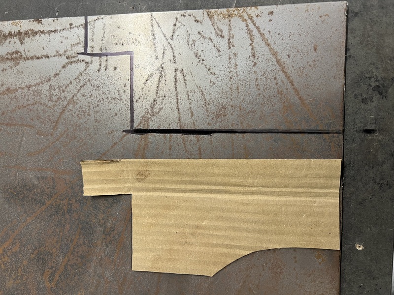
Then a little CAD (cardboard aided design) to mock up the patch piece that I needed.
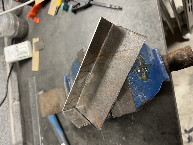
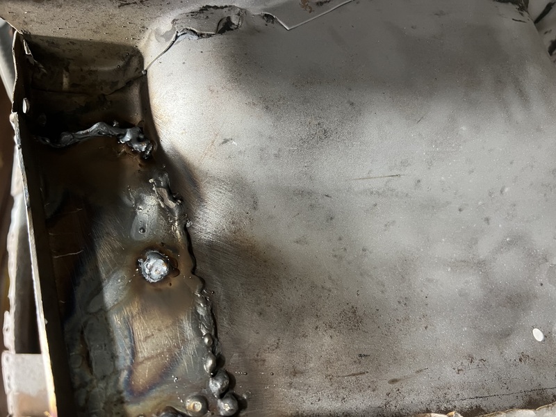
Then some very ugly welding to attach the patch. It’s not pretty, but it won’t be visible when the car is back together. I’ll slather it in sealant before final painting.
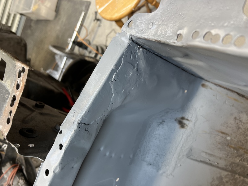
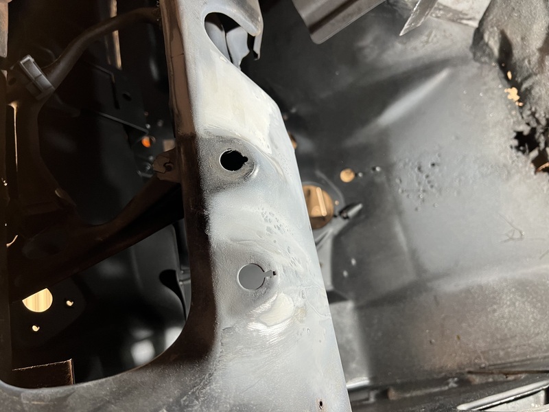
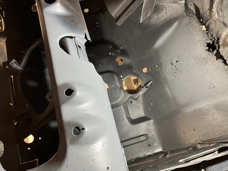
Next up was the issue of attaching my new cowl tank. I primered and painted some of the foot well area. I’ll need to replace some of the floor, so, no point in painting the whole thing, just the parts that will be hard to reach once the new cowl tank is in. I also ran some sealant along the sides. Again, this will be a pain to reach when the cowl is back in, so, easier to deal with it now.
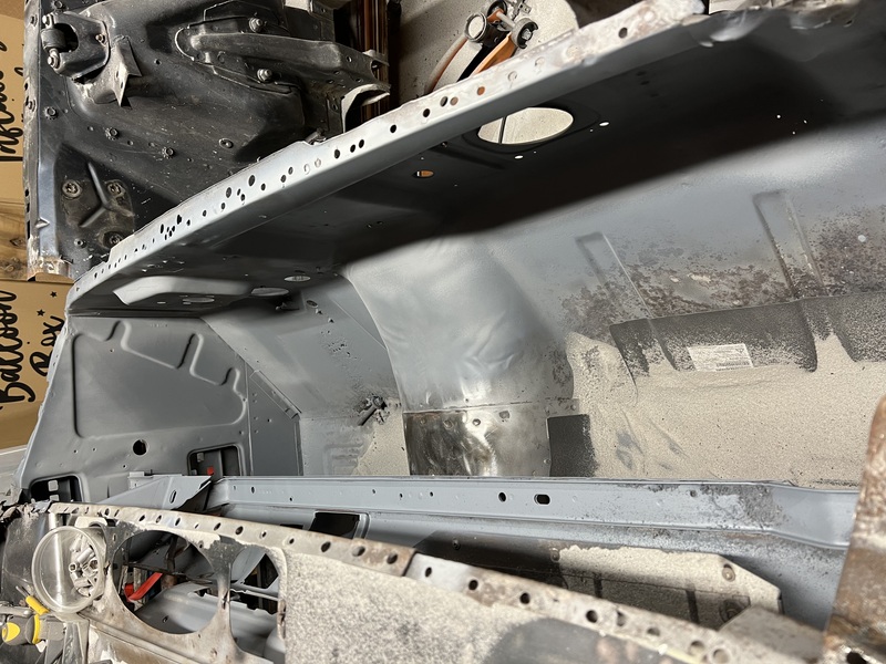
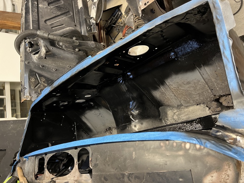
The cowls themselves need to be sealed. Ideally I don’t want to ever have to do this job again. So I’m not taking any chances.
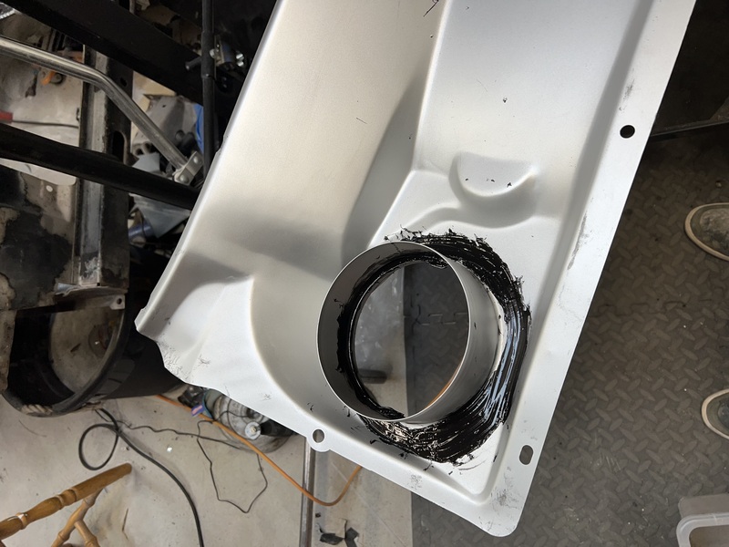
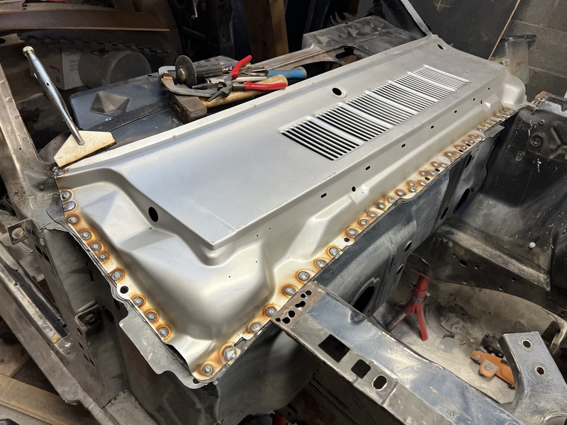
The cowl tank comes in two halves - the lower part and the upper part. Some people will weld the two pieces to each other before welding the whole thing into the car. While other people will weld the two pieces in one at a time. I opted to weld them in one piece at a time. I figured it would be easier to get the fit right doing it this way around. I can more easily do the little bends I’ll need to do to one piece at a time. The two pieces together make a sort of box shape which is much stronger and will be impossible to bend. The downside (I now realise in hindsight) is that there should be a few welds between the lower and upper piece alone the edge just below the windscreen. With the two pieces in, I can’t see exactly where they overlap, so I don’t want to go blindly drilling holes there for welding. I’m going to just leave it and hope that the two pieces don’t rattle against each other.
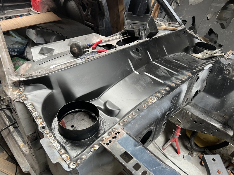
I drilled little holes all along the perimeter of the lower half. I then welded into the holes, attaching the lower half to the car. Not every weld ‘caught’ on the first try. So, I ground them all down, drilled new holes next to the first attempt and tried again. After a while I started to get the hang of it.
I needed to put a little cut into the new metal where windscreen column meets the car. The curve of the new piece is a little less than that on my car. This allowed me to tap in the edge to smoothly line up.
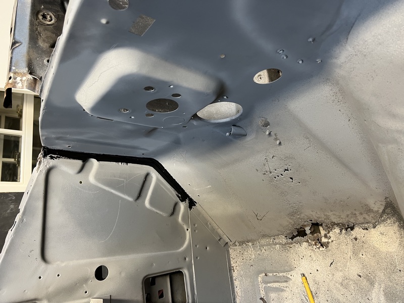
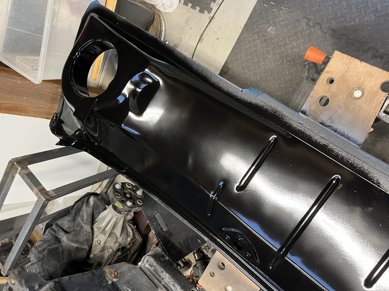
I then ground down all of the welds again to make a flat surface for the upper cowl half to mate with. I primed the perimeter again as all of the paint had been removed from the welding/grinding. I don’t want to leave any bare surface here that car rust up. Especially in this area where water will be flowing through.
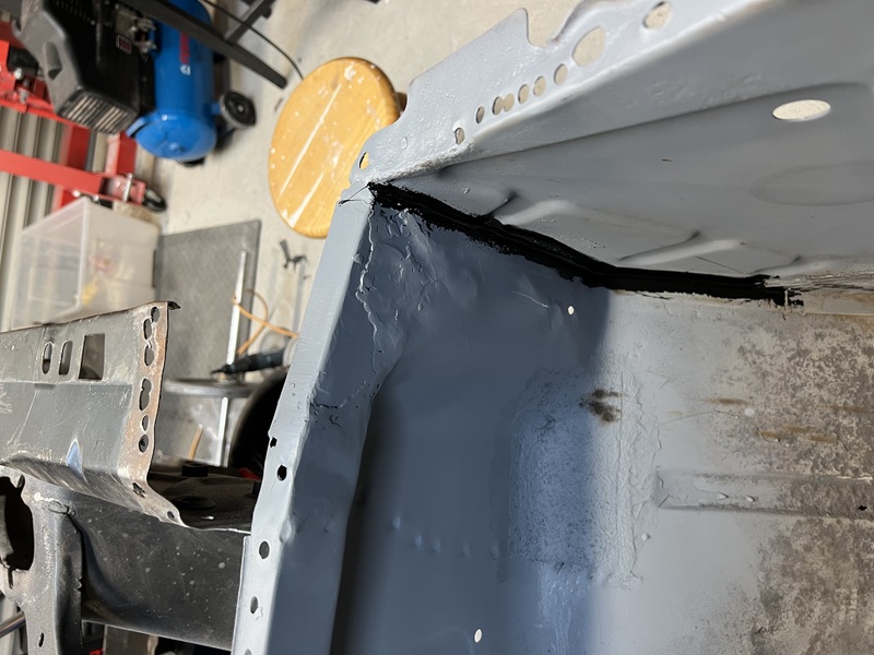
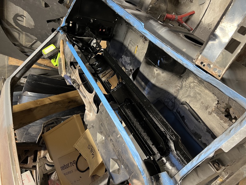
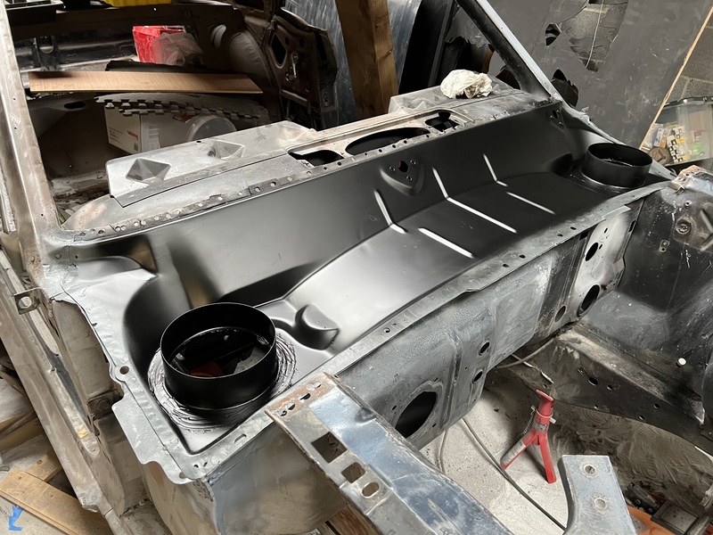
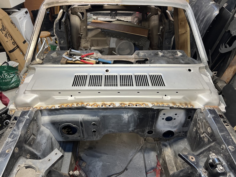
I drilled holes all around the perimeter of the upper cowl half and welded it down the same way. It much easier this time around as I had a much better feel for doing it at this point.
The electrical cable on my welder isn’t quite long enough, so I couldn’t reach the left hand side of the car, so, the remaining welds are left for another day. But very happy with how neat it all looks now. I’ll grin the welds down again one final time to give a tidy looking surface, then prime and seal all of the edges very thoroughly.
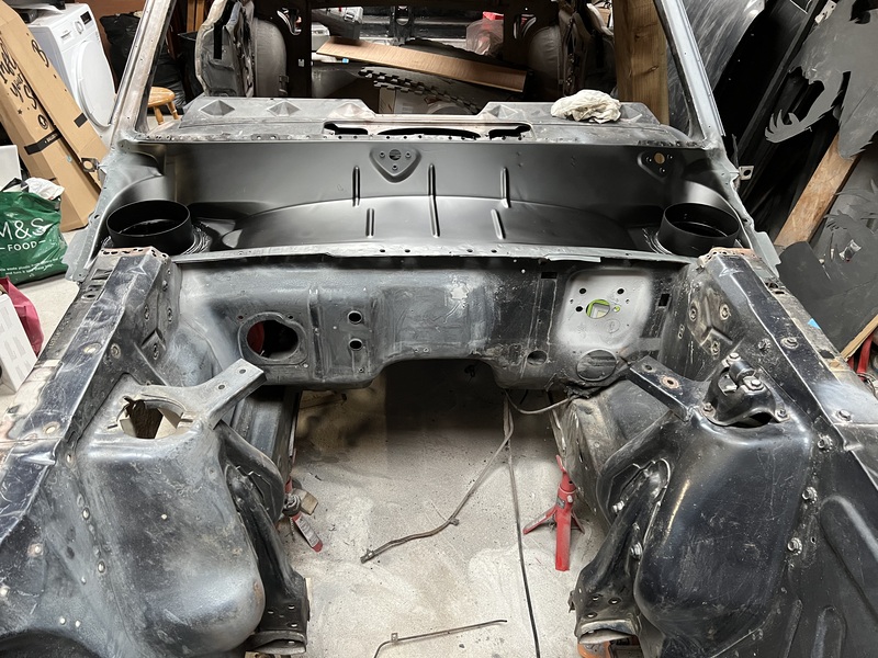
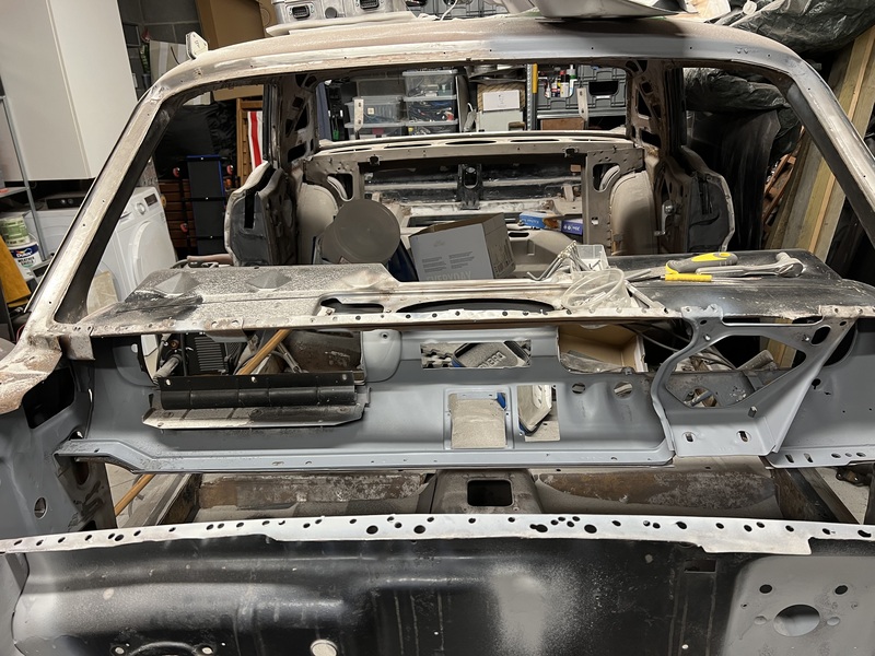
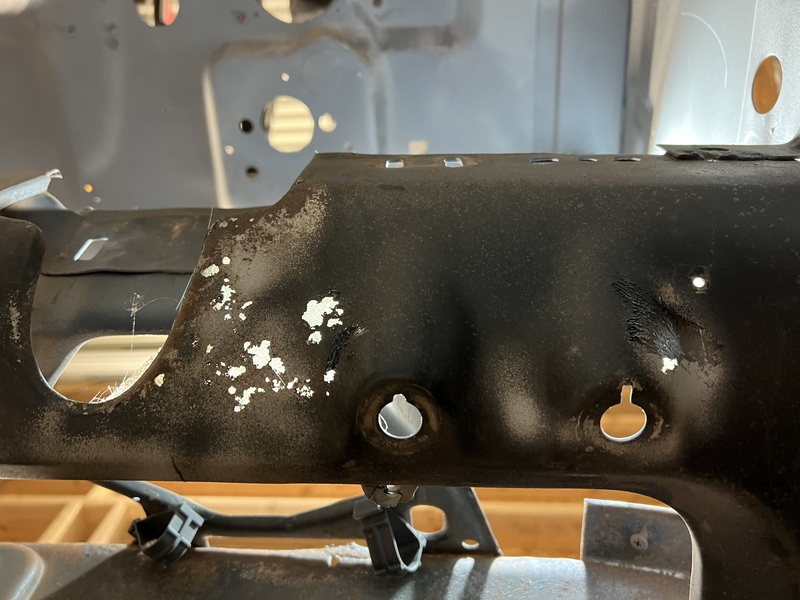
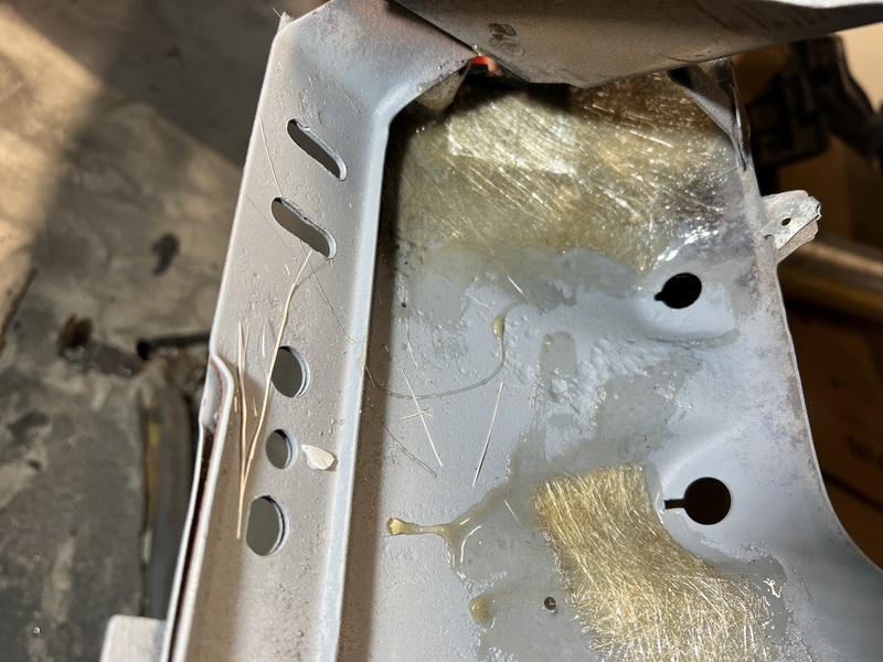
In parallel with all of this, I’ve also been trying to deal with some rust in the dashboard. You can see how near the steering column, there are quite a few holes, some of them quite big. Simply filling this with body filler wasn’t going to work. The gaps were too big for the filler to span. I put some glass fiber on the back of the dash over the holes and let that set. This gave a surface for the filler to grab onto. I filled it, sanded it down and went over it with primer. The paint is a bit messy, so will need to be sanded and painted again, but this looks to have done the job. Much easier and cheaper than replacing the whole dash.
The other area I’ve been working on is the battery management system (BMS) for the car.
I plan to use two battery packs from BMW PHEV cars in the mustang. The packs are around 9kWh each and have a nominal voltage of around 350V. One will go in the area where the fuel tank used to be and one will go in the engine bay. These will be wired in parallel with each other. If I were using only one of these packs, I would just use SimpBMS as the BMS and call it a day. It can already manage these batteries. However, running two packs in parallel introduces some complications. For one, SimpBMS can only deal with one of these packs at a time. SimpBMS has one CAN interface and you need two CAN interfaces to talk with two packs due to overlapping CAN message ids. I could use one SimpBMS per pack, but I would still need some other piece of hardware/software to manage the SimpBMSes. For example, I’ll need to deal with situations where the packs might drift from each other and one pack ends up with a higher voltage than the other. If this drift gets too big, then when we connect the packs together there could be a large uncontrolled current flow from one pack to the other.
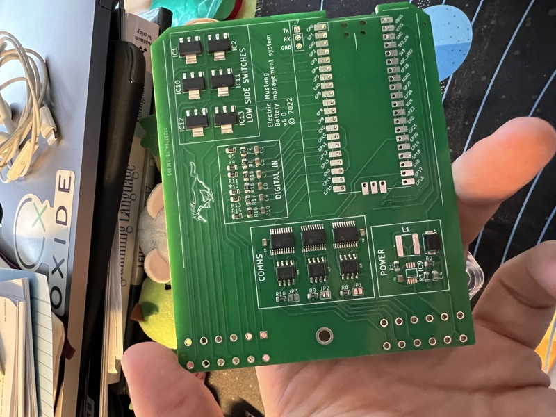
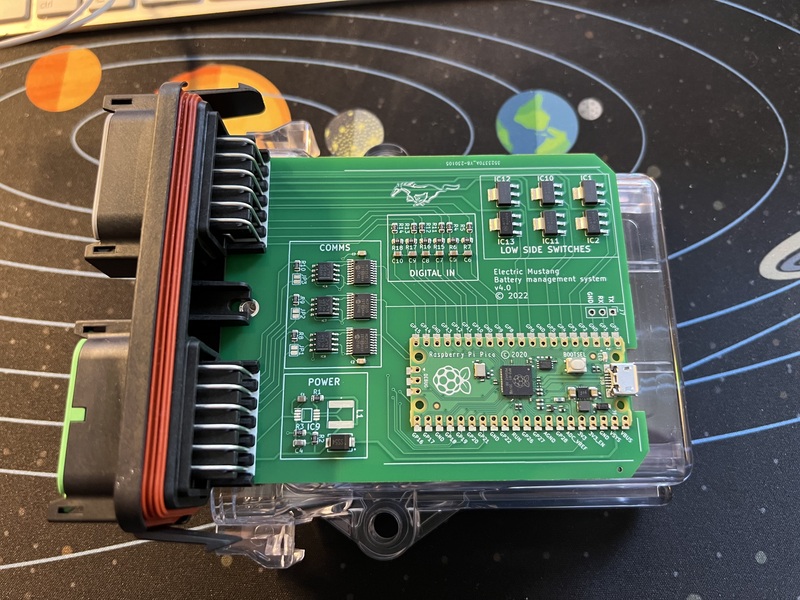
So I’ve started to develop my own hardware/software that will work in a very similar way to SimpBMS. It’s based on the Raspberry Pi Pico board. I started working on this in the middle of the chip shortage. If I had started at another time I would have likely used an STM32 or similar, but these little boards were still readily available, so that’s what I landed on.
My board has three CAN interfaces. One to talk with each battery pack and a third to talk with the rest of the car. Two CAN interfaces would probably be fine, but since I was creating custom hardware I figured I would just use three. The board also has six low-side switches and six digital inputs. Almost every pin on the pico is used for something. The low side switches will be used for things like automatically turning on a battery heater when I’m charging in very cold weather or disallowing driving when the battery is empty. The digital inputs will be used for things like the CHARGE_ENABLE input (signal from the charger that we’re currently charging, to prevent e.g. accidental drive away) and IGNITION_ON signal.
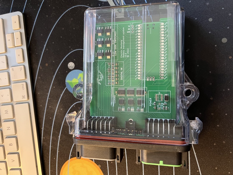
The code is by no means complete, but the basic framework is there. It implements a simple state machine where the BMS moves from one state to another based on input signals. E.g. Idle, charging, driving, battery_empty, and so on. You can see the code here. I also designed it to fit in this snazzy transparent case so you can see what’s going on.