Update #32 - BMS design #
In the last post I mentioned briefly that I was designing a Battery Management System (BMS) for the EV Mustang. I’ve been trying to gather information on BMS design from different sources and apply it all to the design of my system. So, I thought it would be good to do a post solely about that.
What batteries am I using in my conversion? #
I’m planning to use two BMW PHEV battery packs in my EV conversion. One will go in the area where the fuel tank used to be and the other will go in the engine bay. The packs will be connected together in parallel. I’m using two packs to improve my range.
Each pack is made up of 6 modules and each module has 16 cells making a total of 96 cells in each pack and 192 cells in total in the car. The nominal voltage of the pack is 351.4V. BMW puts the official voltage range of the pack as 269V when empty to 398V when full. This puts the ’empty’ cell voltage at 2.8021V and the ‘full’ cell voltage as 4.1458V.
There is a lot more detailed information on these packs over on the openinverter wiki.
Each module has its own BMS slave circuit attached called a CSC. The BMS slave circuit has all of the cell taps for measuring the 16 individual cell voltages and balancing the cells (bringing their voltages back to the same value if they drift apart). It also has three thermistors for measuring the temperature at different points in the module. Also included in the original BMW battery box with the modules is a BMS master circuit. The master communicates with all of the slave modules via a private CAN bus network. The master aggregates all of the data from the slave modules and communicates the overall battery status back to the car.
The message format that the BMS master and BMS slaves use to talk to each other has been reverse engineered and has been implemented in the open source SimpBMS project. You can ditch the original BMS master circuit, replace it with a SimpBMS and use this battery in your own application. SimpBMS includes all of the functionality that you would want - cell voltage monitoring, temperature monitoring, and balancing.
Why am I creating a custom BMS? #
Why not just use SimpBMS if it can already manage these battery packs?
I mentioned earlier that the communication protocol had been reverse engineered. Each module in the pack (when requested) will send out a series of CAN messages reporting the status of the cells in that module. The ID of these messages corresponds to a particular module in the pack. I.e., module #1 has CAN ID 0x2X, module #2 has CAN ID 0x3X, … etc. What this means is that if we put two battery packs on the same CAN network, then you’ll have two modules transmitting with the same CAN ID. You won’t be able to tell the two module #1s apart and the two module #2s apart and so on. If you want to have two of these battery packs, you need to have them on two separate CAN networks. SimpBMS runs on a Teensy 3.2 and this device only has one CAN network. So, as is, SimpBMS can’t natively support two packs on two networks.
I could get two SimpBMS and connect each one to a private CAN network with one of the packs. But I would still need another device which would aggregate the data from the two SimpBMS and report and overall status to the car. Plus, this other device would probably still need three CAN interfaces - one to talk to the car, and one for each of the SimpBMS. You can see that we’re already half way to implementing a custom BMS here anyway.
Paralleling packs also adds some complications. A safety rule of thumb is to not have any high voltage outside of the battery box when the car is off. This means that the packs will not be connected together when the car is off. There is a risk, albeit small, that the packs could get out of sync with each other. I.e., one pack could end up in a higher/lower state of charge than the other and therefore have a different voltage. When you connect these two packs together, the risk is that you’ll have a large uncontrolled current flow from one pack to the other. So, I want to implement functionality to disallow paralleling the packs when their voltage difference is above a certain level. Again, this is not something that SimpBMS implements.
Any other problems? #
If I weren’t a masochist, I would just implement simple logic to disallow driving/charging if the pack voltages differ by too much. But I can’t leave it at that I guess. I’ve made the logic/features a little more advanced.
Even if the pack voltages differ the BMS could fail a little more gracefully. You could still close the contactors for one of the battery packs and allow the car to drive, albeit with a reduced range. In fact if you close the contactors for the battery with the higher voltage, the car can then ‘drive off’ some of the energy from the high pack and when the packs get back in sync with each other, you can allow the contactors for the other pack to close. This would allow automatic re-syncing of the packs.
The same strategy can be used for charging. If the packs get out of sync and you want to initiate a charge, you can close the contactors for the low pack to allow charging. Then, when the low pack has been charged up to the level of the high pack you can allow the high pack contactors to close and the two packs are back in sync again.
There are some corner cases here which are hard to deal with automatically however. Say your packs are out of sync. You turn the car on and go for a drive. The ‘high’ pack will be enabled. You pull up to a charger and you want to charge the car, but you have not yet driven off enough energy from the high pack to get them back in sync. Going directly from drive mode to charge mode won’t work. The charging process will want the low pack to be enabled. But the high pack is enabled because you’re in drive mode. What the BMS will do here is just error out. Simply turning the ignition off will fix the issue. The car will go into standby mode, the contactors will all open and then when charging is initiated the low pack contactors can close instead.
Contactor control #
Contactor control can be a bit of a controversial topic. The general consensus seems to be that you either allow the BMS to control your contactors or you allow your inverter to control your contactors. I think this rule is generally sound, but, at least in my case, there are some extra complications and nuance that also needs to be considered.
I only want high voltage where it needs to be when it needs to be there. This means I need quite a few contactors.
- The high voltage junction box will have four contactors (precharge, main, charging positive, and charging negative)
- The rear battery pack will have two contactors (positive and negative)
- The front battery pack will have two contactors (positive and negative)
I’ll also have CCS and CHAdeMO contactors, but I’m not including them in this list as they’ll definitely be controlled by the charge controllers.
The HVJB precharge and main contactors will be controlled by the inverter. It already has logic for dealing with precharge, checking for HV and bailing out if there are issues. No point in trying to re-invent that wheel.
All of my charging equipment will be in the rear of the car, but my shunt will be in my HVJB in the engine bay. When charging I want all of that current to flow ‘backwards’ through the shunt so I can accurately track the SoC of the batteries. I’ll need charge cables running from rear to front. But I don’t want these cables connected to the batteries unless I’m actually charging. Hence the need for the charging contactors in the HVJB.
That leaves the battery box contactors. I want these contactors to close when the car is in drive mode or charge mode. My first thought here was that I should have the BMS directly control these contactors. The BMS knows when we are in drive mode or charge mode via the IGNITION_ENABLE and CHARGE_ENABLE signals (see below). But after a bit of thought this seems backwards. I would be depending on the BMS actively holding the contactors closed all of the time when driving or charging. What if I have a bug or some electrical noise interferes with the BMS? Doing it the other way around might be more reliable. That is, by default allow the contactors to close. But allow the BMS to step in and actively open the contactors if required. This is what I plan to implement.
It’s also worth noting though that while opening the contactors might seem like a good thing to do when ‘something bad’ happens that’s not necessarily always true. For example, when you’re driving along, there is quite a bit of energy stored in the magnetic field of the motor. When this collapses the energy is released. Normally the battery will absorb this. But if you’ve opened your contactors this can’t happen. And in some cases this can kill your inverter.
For this reason, I plan to only allow the BMS to open the contactors in certain specific circumstances. In fact, it’s more accurate to think of it as the BMS inhibiting the contactors from closing at some future time rather than opening already closed contactors.
So, in a sense, because I have two layers of contactors I have both the inverter and the BMS control the contactors.
What other features will the BMS have? #
Charging in cold weather #
Charging lithium ion cells when their temperature is below freezing can damage them. The BMS will block charging and turn on a battery heater if any of the temperature sensors are below a certain level. Probably 3 degrees Celsius or so to leave a little margin for error. Once the temperatures have risen to an acceptable temperature, charging will be allowed to begin and the heater will be turned off.
I’ve not decided what I’ll use to heat the batteries just yet. Possibly a few 12V heating matts stuck to the bottom of the battery boxes.
Temperature management #
I also want to prevent the batteries from overheating. When driving I don’t anticipate a lot of issues here. The main concern is around charging, especially DC fast charging. The BMS will provide a max charging current limit to the charger. This will vary depending on battery temperature and possibly also SoC. I’ll need to find this temperature vs charge curve by trial and error.
Hardware design #
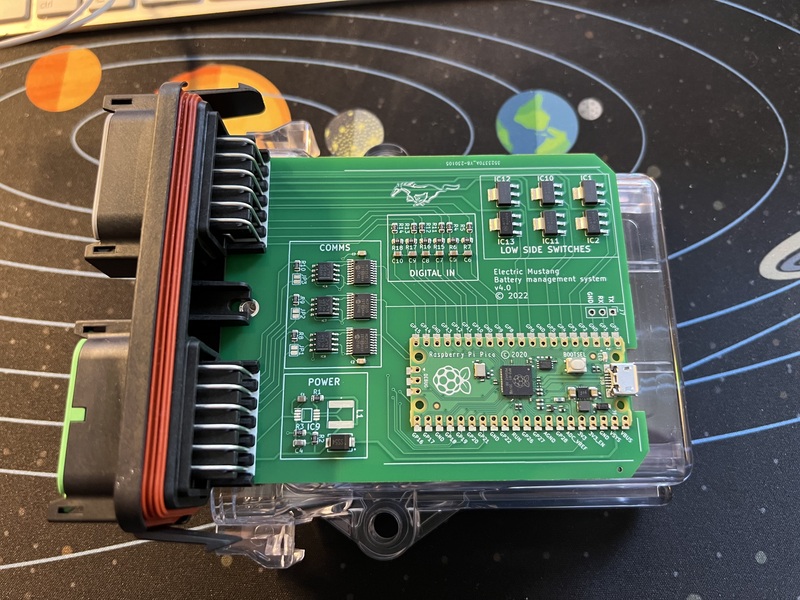
The hardware design is open source. You can find the the KiCad files here.
The BMS uses the Pi Pico as its microcrontroller.
It has three CAN bus ports connected to the SPI bus of the Pico. One CAN port is for communicating with the car. The other two CAN ports are for communicating with the batteries.
The latest version of the hardware has six digital inputs and six low side switches.
Digital inputs #
IGNITION_ENABLE - this allows the BMS to detect when the ignition has been turned on and drive mode is being requested.
CHARGE_ENABLE - this is a signal from the charge controller. It allows the BMS to detect when charging has been requested.
The other four inputs are held back for future use.
Low side switches #
BATTERY_HEATER - This allows the BMS to turn on the battery heaters. It will switch on a relay which will power the heaters.
DRIVE_INHIBIT - This signal allows the BMS to tell the rest of the car that driving is not allowed. The inverter has simple digital FORWARD and REVERSE signals. If FORWARD is high, then the motor will spin forwards when the accelerator is pressed. If REVERSE is high, the motor will spin backwards when the accelerator is pressed. If the inputs are in any other state, nothing will happen. I’m going to pass the FORWARD and REVERSE signals through the normally closed side of a relay. The DRIVE_INHIBIT signal will be wired to switch this relay. When DRIVE_INHIBIT is high, the relay will be switched ‘on’ which will disconnect both of the FORWARD and REVERSE signals.
There are a few different situations where the signal will be used.
The BMS will monitor the cell voltages. If any cell gets to the minimum voltage (2.8021V according to BMW) the battery is empty. We don’t want to extract any more energy or we could damage it. When in drive mode the DRIVE_INHIBIT signal will be used to force the car to stop (or not start) to ensure we stop extracting energy from the battery. We’ll do this rather than opening the contactors because of the risks describe above.
The DRIVE_INHIBIT signal will also be used to halt the car when the battery is at risk of overheating when in drive mode. Again, this is preferential to opening the contactors.
Finally, the DRIVE_INHIBIT signal is used to prevent accidental drive away when the car is charging.
CHARGE_INHIBIT - This signal allows the BMS to tell the charge controllers that the car is not ready to charge. This could be because the battery is too cold and we’re waiting for it to warm. It can also be used when the battery is full and we don’t want allow the charge process to begin at all.
BATTERY_INHIBIT_FRONT and BATTERY_INHIBIT_REAR - these signals are used to inhibit future attempts to close the contactors for that particular pack. These work in a similar way to DRIVE_INHIBIT. The signal for the battery box contactors go through the normally closed side of a relay. By default, the contactors can be closed. But the BMS can turn this relay ‘on’ and inhibit the contactor from closing. The primary use for this will be when the battery packs are out of sync with each other.
Software #
The software is open source. You can find the current version of the BMS code on Github here.
The code implements a simple state machine. There are 5 possible states - standby, drive, charging, batteryEmpty, and fault. Each state is a function. The current state is a pointer to the function corresponding to that state. Each time some event happens, we just pass the event to whatever the current state function is and it works out what to do with it. This approach makes it quite simple to reason about the logic. I’m in state X and I get event Y - what happens?
To do #
- Confirm that the hardware design of the power supply works
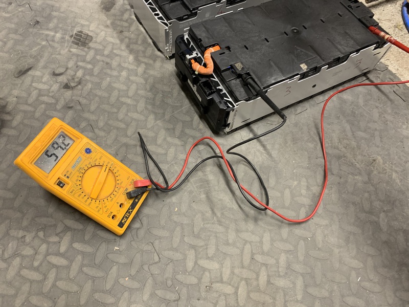
- So far I’ve only tested one module at a time. Perform a full test will all modules from both packs connected at the same time.
- The BMS does yet send out status messages on the CAN bus. Look to see if there are common patterns used here and try and follow them. Look at SimpBMS, Orion and so on and see if there is any common message IDs or message formats.
- Implement cell balancing
- Fetch Ah/kWh data from shunt to calculate SoC estimate
- Test charge limits functionality - this will come much later when the car is on the road
- Provide range estimate. I may not implement this in the BMS. I will have a ‘dashboard’ vcu which will aggregate data from the various components in the car. This functionality might be implemented there.
- Possibly look at implementing state of health functionality