Battery Management System #
Overview #
I have implemented my own BMS including both custom hardware and software.

Code for my BMS is over here.
The hardware was designed in KiCAD. You can see all of the project files here.
This project leverages earlier work by Tom DeBree in his SimpBMS project/product. I will resuse most of the OEM BMS system. Each battery module has a ‘slave module’ attached which directly monitors the cells in that module. In the original application, a ‘master’ module collects data from all of the slave modules. Thanks to the fact that SimpBMS is open source, I was able to see how the communication between the OEM BMS master and slaves works in the BMW PHEV battery packs and re-implement it in this project. My BMS essentially replaces the original master module.
Features #
Below are a list of features that are or will be implemented in the BMS.
- Monitor the voltages of all cells.
- Monitor the temperature of all modules.
- Emit DRIVE_INHIBIT signal to disallow driving when the battery is empty or when the car is charging.
- Emit the CHARGE_INHIBIT signal to disallow charging and disable regen when battery is full.
- Transmit charge current limits based on battery temperature to prevent overheating when charging.
- Disallow charging the battery when it is too cold in order to prevent damage.
- Control battery heater when attempting to charge in cold conditions. Warm battery to safe temperature before commencing charging.
- Protect against risks associated with the two battery packs drifting apart in terms of SoC/voltage. See below.
Overview #
The design of the BMS assumes that it is powered on 24x7. I’ve not looked at the total power consumption yet, but this is probably a hit I’m willing to take to simplify the design a lot. I also plan to implement a small system to charge the 12V from the high voltage battery if it dips too low so I’m OK with the car having a small parasitic load. I may also implement some sleep/wake functionality to further reduce energy consumption.
Hardware #
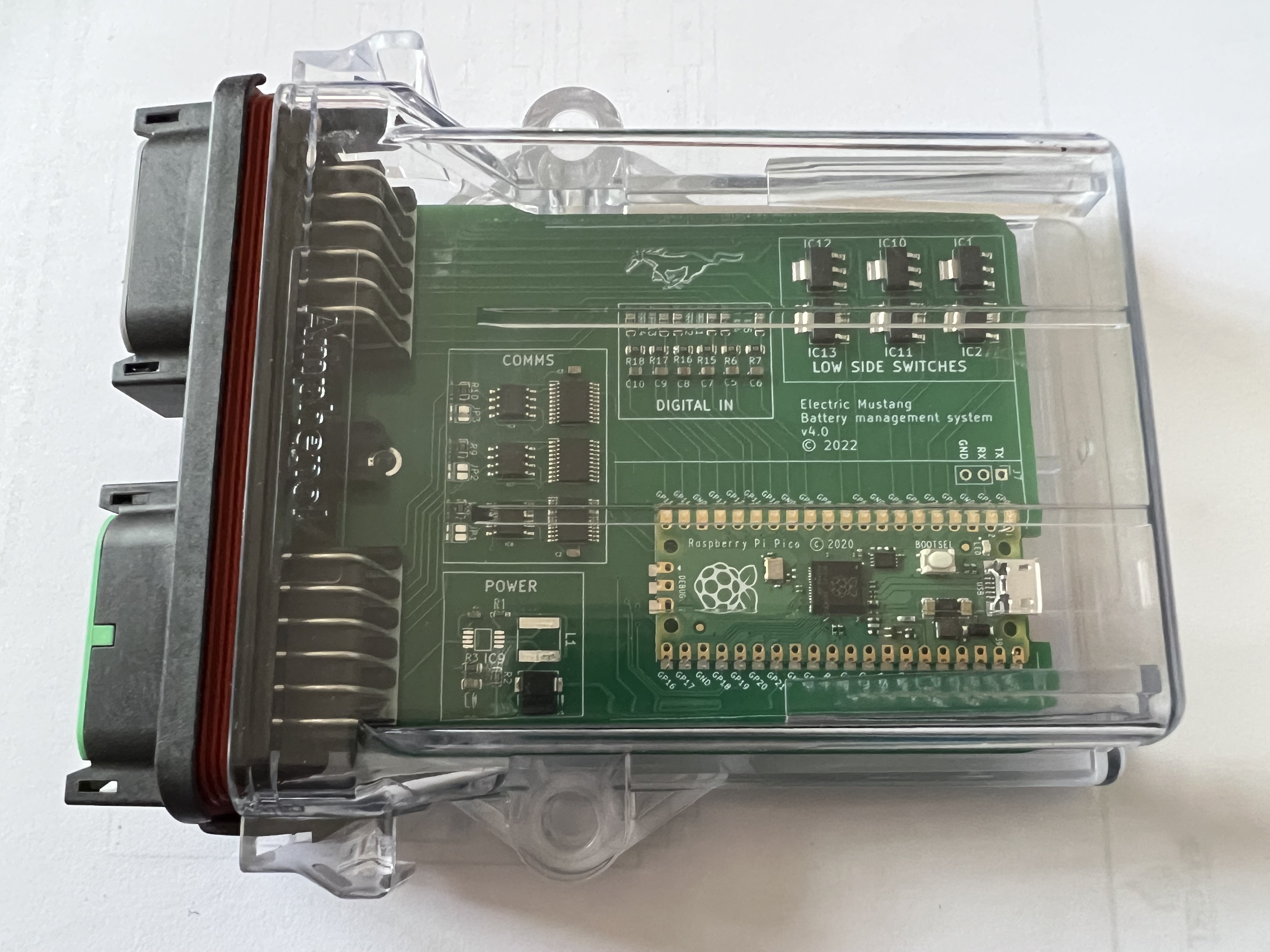
I’ve designed a custom PCB based around the Raspberry Pi Pico.
The board has three CAN bus controllers (MCP2515) connected via SPI to the Pico. The two battery packs will need to be on separate CAN bus networks as they use the same CAN Ids and it would be impossible to tell module #1 from pack #1 from module #1 from pack #2. It probably would have been sufficient to put one battery on the ‘main’ CAN bus network and the other on a private network, but it feels neater to me to have one private network for each of the batteries and one network for the rest of the car.
The board also has six low side switches and six digital inputs. Some of these are spares for future additional features.
The low side switches are for:
- DRIVE_INHIBIT - signal from the BMS to tell the car that we are not allowed to drive right now
- CHARGE_INHIBIT - signal from the BMS to tell the charger we are not allowed to charge
The digital inputs are for:
- IGNITION_ON - signal from the car to tell the BMS the ignition is on
- CHARGE_ENABLE - signal from the charger to tell the BMS that we’re trying to charge right now
- HEATER_ON - signal to turn on the battery heater
Drive inhibit signal #
If the battery is empty, we don’t want to allow the car to drive.
We need to be careful here. Disabling high voltage in a moving vehicle can destroy your inverter. The DRIVE_INHIBIT signal will not disable high voltage, but rather force the car into neutral.
Charge inhibit signal #
If the battery is full, we don’t want to charge it any further.
We also want to avoid accidental overcharging by regen. I’m not sure how this will be implemented yet, but this signal could perhaps be used.
Charging a lithium ion battery at cold temperatures can damage it. A rule of thumb is to never charge a battery if it’s temperature is below 0 degrees C. The BMS monitors the temperatures of the battery modules and enables the CHARGE_INHIBIT signal if they are too cold to charge. If we see the CHARGE_ENABLE signal enable, then the BMS will turn on the heaters to warm up the batteries to a suitable temperature to charge. Once they’ve reached a good temperature, the CHARGE_INHIBIT signal will be disabled.
Paralleling packs #
I initially bought one BMW PHEV battery pack, thinking I would use that alone as a ‘starter’ pack. Then, later down the road, I’d pick up a larger pack and swap it in - once the car had been proven. However, a second BMW PHEV pack came up for sale, and I couldn’t resist, so now I have two of them to put in the car. I will use them in parallel in the car to double my range.
Paralleling packs brings some extra complications with it.
First of all, it’s not wise to have the two packs permanently paralleled with each other.
I want high voltage to be only where it needs to be, when it needs to be there. When the car is off, for example, there should be no high voltage anywhere but inside the battery boxes. Each battery box then needs its own set of contactors.
The battery packs will also charge and discharge slightly differently to each other for various reasons.
- There will be small manufacturing differences because the packs were created at a different time to each other (difference of years).
- The two packs are from different cars. They would have been used for a different amount of time (i.e., a different age), and had a different use profile.
- One pack will be located in the engine bay while the other will be located in the rear where the fuel tank used to be. While driving I can probably expect them to have somewhat different ’thermal experiences’ which will impact how they charge and discharge.
What this means is that it’s possible that the packs could drift a little apart in terms of their SoC and voltage. If that drift becomes large, there is a risk that when you parallel the packs together, you get a large, uncontrolled current flow from the ‘high’ pack to the ’low’ pack. This may blow my pack fuses, or, worse start a fire.
For this reason, my BMS will monitor the voltage of each pack and ‘inhibit’ the closing of contactors when the voltage delta between the packs goes over a certain limit.
In fact the BMS will take this a step further. Even though the packs may be out of sync with each other, we can still safely use one of the two packs. When going into drive mode, the BMS will allow the contactors for the ‘high’ pack to close. This will allow me to drive, but also, I can drive off some of the extra charge in that pack and when it drops to the same level as the ’low’ pack, we can then close the contactors and we’re back to ’normal’. The same process can be followed for the charging, but the opposite way around. When going into charge mode, close the contactors on the ’low’ pack only. As the ’low’ pack charges, its voltage will come up to that of the ‘high’ pack and it can then close those contactors.
Balancing #
The SimpBMS project has implemented cell balancing functionality. I’ll re-implement this functionality in my BMS based on the SimpBMS code.
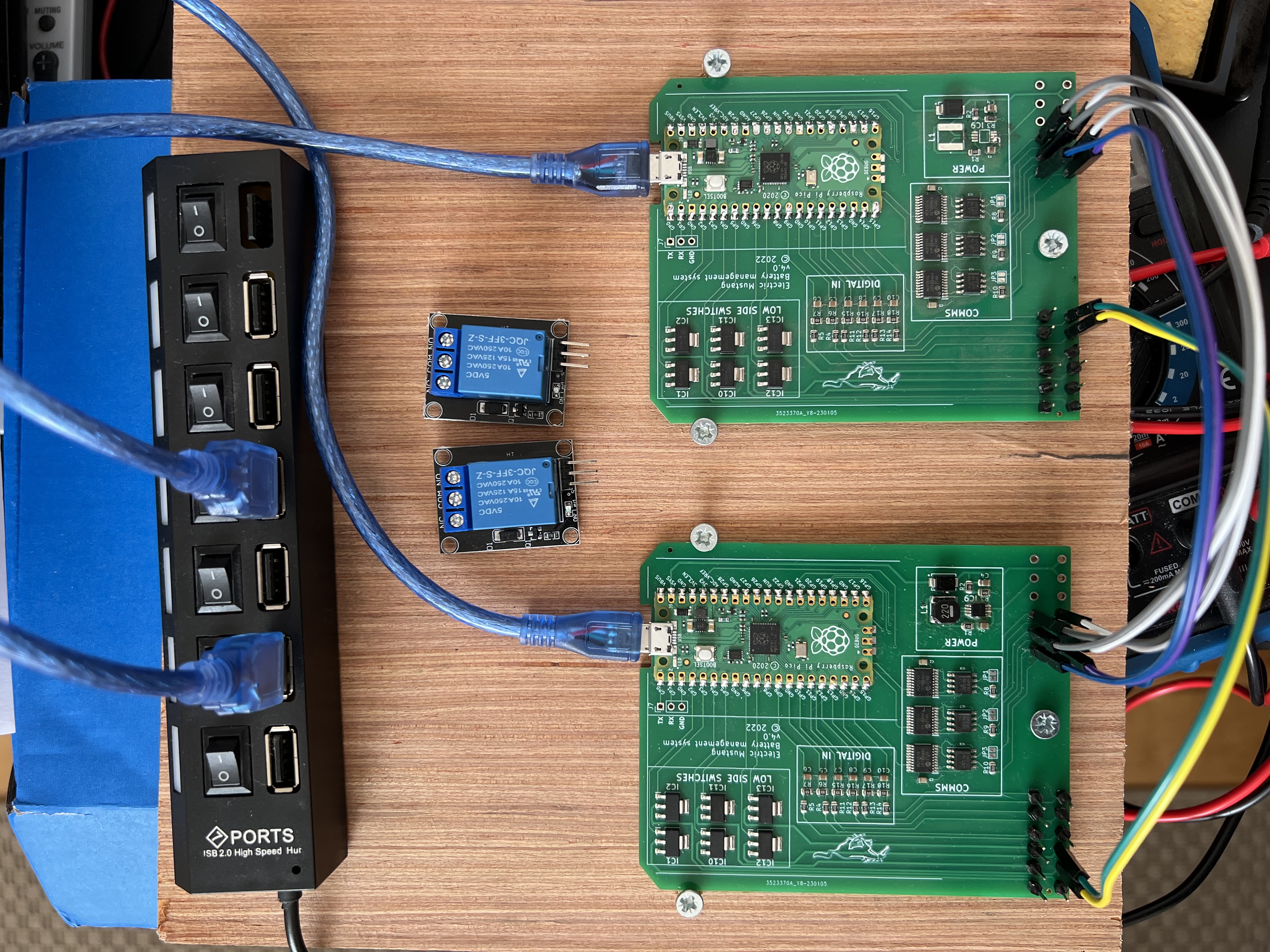
Testing #
I plan to automate testing of the BMS. To achieve this, I’ll use two of the BMS boards. One will run the actual BMS code. The other will run special testing code which will simulate all of the signals generated by the car. The testing code will generate specific error conditions and make sure that the BMS reacts in the correct way. E.g., when one of the battery cells are empty, it should enable the DRIVE_INHIBIT signal.
