Update #16 - First spin #
2020-10-29
The next step in the Mustang EV conversion project was to do some bench testing of the inverter and motor together. After all, as far as I know, these two particular pieces of hardware have probably never been hooked up to each other by anybody. The inverter has come from a Toyota Yaris, while the motor comes from a Lexus gs300h.
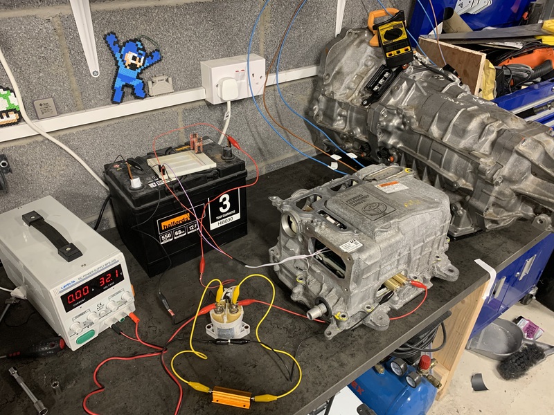
Here’s the bench setup.
First, I needed 12V to power the OpenInverter board inside the inverter. Initially I used a car battery for this. But, it had been sitting on a shelf for quite some time, so there wasn’t much charge in it. So, after a while I use just used the power supply from a PC for this instead. I just stuck a little jumper wire between pins 3 and 4 on the PSU and took 12V out from the floppy drive connector.
I also needed a 12V signal into the MG2_FORWARD pin on the OpenInverter board to tell it to drive the motor forward.
Next up I needed a ‘high-voltage’ supply. Something which would simulate the job of a battery, but with lower current and voltage for some basic testing. So I don’t blow anything up. For this I’m using a bench power supply capable of 30V and 5A.
I’m also using one of my contactors to simulate how they will be used in the final car. In the final car, the high voltage batteries will only be ‘on’ (connected to the inverter) when the car is on. Since I will be connecting/disconnecting high voltage DC, I need to be careful to choose something that will actually be able to break a DC current. This is why contactors are used instead of relays. We also have to be careful when switching the battery on. There is a large capacitor in the top of the inverter. If we don’t restrict the current flow when we turn the battery on, there will be a large current inrush and that capacitor will blow up. So, we have to use a large resistor to restrict the current flow when we initially connect the battery. This is called the precharge resistor. Once the capacitor is charged, we can bypass the resistor and allow the full current to flow for normal driving. The orange thing is the precharge resistor. The white cylindrical thing is a contactor.
And, finally, I have three phase wires connecting from the inverter over to the MG2 motor in the Lexus CVT.
With a bit of basic setup of the OpenInverter parameters, I could get the motor spinning in open loop mode.
This is my first big milestone complete. I’ve proved that I can turn the motor. Next up is time for some higher power tests and to start tuning the settings so I can do proper throttle control of the motor.
