Low Voltage Wiring #
When I bought the car, the wiring was in a pretty sorry state. Lots of the insulation had become brittle and even broken off in some places causing shorts. One way or another, the low voltage wiring was going to need a major overhaul.
Converting the car to an EV also means there will be a lot of additional components powered from the low-voltage wiring (inverter, charger, contactors, etc.). Not only that, but we want some additional logic in the low voltage system such that different sets of components are powered on in different circumstances. Specifically, I want to differentiate between when the car is in ‘drive’ mode and when the car is in ‘charge’ mode. Some components will be only be powered on in one of the modes (e.g., charger should only power up in ‘charge’ mode), while other components will be powered in both modes (e.g., the coolant pump needs to be powered on in ‘drive’ mode and ‘charge’ mode).
One option would be to purchase a replacement wiring loom for the car and then modify it for my needs.
In the end, I decided to opt to build a new low voltage system from the ground up.

The low voltage system is broken into three ‘boards’.
- Front board
- Lighting board
- Rear board
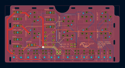
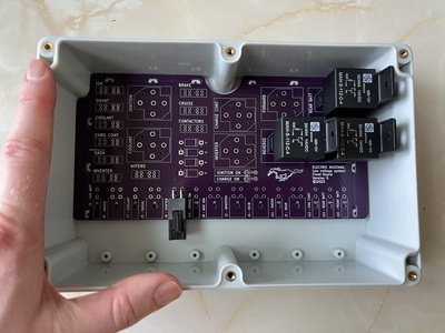
Front Board #
This is the main board for controlling the low voltage system. The ignition and selective powering of the different components happens here.
- Inhibiting driving logic
- Selective powering of components when ignition is on vs when charging
- Sends ignition on signal to other boards
- Permanent power to certain components, e.g. ISA Shunt
- Control of charging contactors
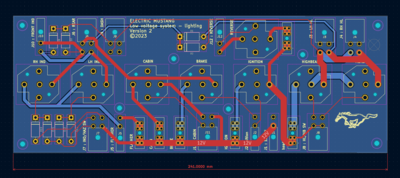
Lighting Board #
This board is responsible for all lighting circuits in the car.
- Headlights
- Indicator/turn signal lights
- Brake lights
- Cabin Headlights
Rear Board #
This board controls all of the devices in the rear of the car.